72
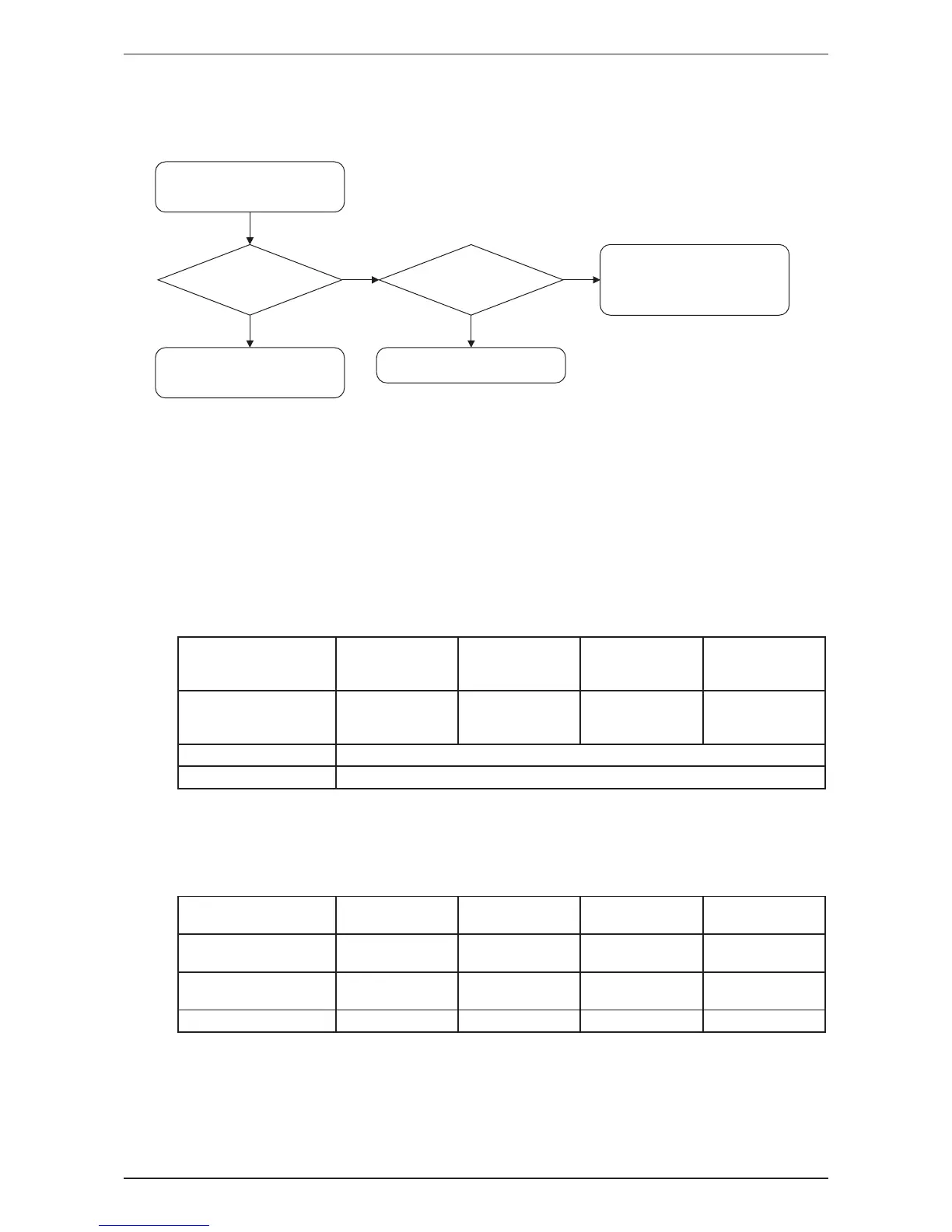
6.7 Outdoor fan system check
Outdoor fan running?
No
DC motor
Yes
No
Fan motor
lead wire connector
disconnected?
Refer to
Appendix A Rotation pulse
check on outdoor unit PCB.
Outdoor fan system is
functioning.
Yes
Check the outdoor fan
system.
Reconnect the connector.
Refer Page 71, item 6.5
6.8 Diode bridge short circuit check procedures
6.8.1 Power transistor check for class 09 & class 12
Check to make sure that the voltage between the terminal of Power transistor (+) and (-) is approx. 0
volt before checking power transistor.
<Measuring method>
Disconnect the compressor harness connector from the outdoor unit PCB. To disengage the
connector, press the protrusion on the connector.
Then, follow the procedure below to measure resistance between power transistor (+) and (-) and
the U, V and W terminals of the compressor connector with a multi-tester. Evaluate the measurement
results for a pass/fail judgment.
<Power transistor check>
Negative (-) terminal of
tester (positive terminal
(+) for digital tester)
Power transistor
(+)
UVW
Power transistor
(-)
UVW
Positive (+) terminal of
tester (negative terminal
(-) for digital tester)
UVW
Power transistor
(+)
UVW
Power transistor
(-)
Normal resistance SeveralkΩtoseveralMΩ(*)
Unacceptable resistance Short(0Ω)oropen
6.8.2 Main circuit short check for class 18 & class 24
Check to make sure that the voltage between (+) and (-) of the diode bridge (DB1) is approximately
0 V before checking.
• Measure the resistance between the pins of the DB1 referring to the table below.
• Iftheresistanceis∞orlessthan1kW,shortcircuitoccursonthemaincircuit.
Negative (-) terminal of
multimeter
- (2, 3) + (4) - (2, 3) - (1)
Positive (+) terminal of
multimeter
+ (4) - (2, 3) - (1) - (2, 3)
Resistance is OK
SeveralkΩ~
severalMΩ
∞ ∞
SeveralkΩ~
severalMΩ
Resistance is NG 0Ωor∞ 0 0 0Ωor∞
*Remark:
1. Use opposite sign of terminal for digital multimeter for measurement.
 Loading...