■English 5
■
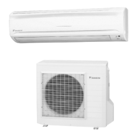
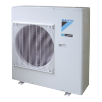
Outdoor Unit
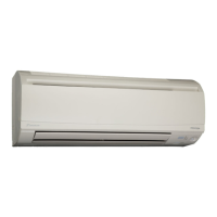
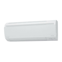
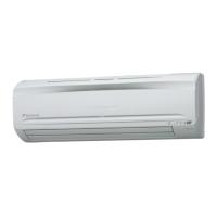
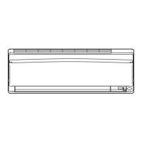
■ Indoor Unit
1. Air filter
2. Air-purifying filter with photocatalytic
deodorizing function:
• These filters are attached to the inside of the
air filters.
3. Air inlet
4. Front panel
5. Panel tab
6. Room temperature sensor:
• It senses the air temperature around the unit.
7. INTELLIGENT EYE sensor:
•
It detects the movements of people and
automatically switches between normal operation
and energy saving operation. (page 18.)
8. Display
9. Air outlet
10. Flaps (horizontal blades): (page 12.)
11. Louvers (vertical blades):
•
The louvers are inside of the air outlet. (page 13.)
12. Indoor Unit ON/OFF switch: (page 10.)
• Push this switch once to start operation.
Push once again to stop it.
•
The operation mode refers to the following table.
• This switch is useful when the remote
controller is missing.
13. Operation lamp (green)
14. TIMER lamp (yellow): (page 20.)
15. HOME LEAVE lamp (red): (page 16.)
16. Signal receiver:
• It receives signals from the remote controller.
•
When the unit receives a signal, you will hear a
short beep.
• Operation start .........beep-beep
• Settings changed ......beep
• Operation stop ..........beeeeep
■ Outdoor Unit
17. Air inlet: (Back and side)
18. Air outlet
19. Refrigerant piping and inter-unit cable
20. Drain hose
21. Earth grounding terminal:
• It is inside of this cover.
22. Outside air temperature sensor:
• It senses the ambient temperature around the
unit.
Appearance of the outdoor unit may differ from some models.
'
&
%
Mode
Temperature
setting
Airflow rate
AUTO 77°FAUTO
01_EN_3P141693-1K.fm Page 5 Tuesday, September 19, 2006 3:46 PM
 Loading...