English
1-1
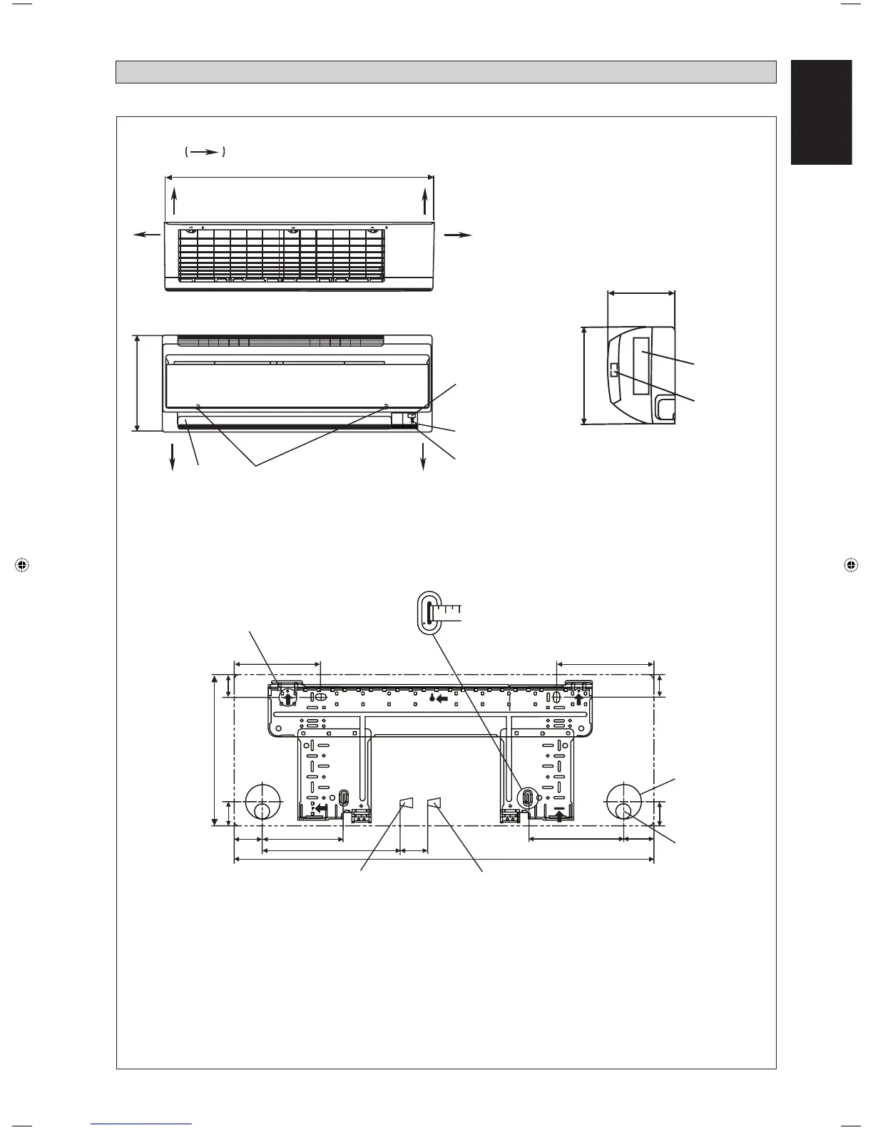
Indoor Unit
A
B
FRONT VIEW
TOP VIEW
C
SIDE VIEW
H
I
B
THE MARK
SHOWS PIPING DIRECTION
REAR REAR
RIGHTLEFT
BOTTOM BOTTOM
FRONT GRILLE FIXED SCREWS
(INSIDE)
LOUVER
SIGNAL RECEIVER
INDOOR UNIT
ON/OFF SWITCH
ROOM TEMPERATURE
THERMISTOR (INSIDE)
NAME PLATE
TERMINAL
BLOCK
WITH EARTH
TERMINAL
F
E
J
G
G
L
D
B
K
M
A
Gas pipe end
INSTALLATION PLATE FTYN25/35LV1B
Liquid pipe end
Through the wall
hole Ø 65mm
All dimensions are in mm
Drain hose position
F
Original Instruction
OUTLINE AND DIMENSIONS
«
Recommended mounting plate
retention spots (5 spots in all)
Use tape measure as shown.
Position the end of a tape
measure at
Ñ
1 EN-5WMJ-1211(0)Daikin.indd 11 EN-5WMJ-1211(0)Daikin.indd 1 1/12/12 1:44:35 PM1/12/12 1:44:35 PM