EasyManua.ls Logo

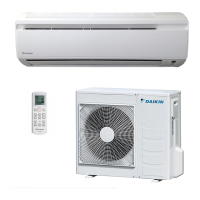
Daikin FTYN35CVMB9 User Manual

Daikin FTYN35CVMB9
246 pages
To Next Page IconTo Next Page
Page #1 background imageLoading...
Page #1 background image
Ser vice
Manual
Inverter Pair
Wall Mounted Type C-Series
D-Series
[Applied Models]
zInverter Pair : Cooling Only
zInverter Pair : Heat Pump
SiENBE04-401A

Table of Contents

Questions and Answers:

Daikin FTYN35CVMB9 Specifications

General IconGeneral
Cooling Capacity3.5 kW
Weight (Indoor Unit)9 kg
RefrigerantR32
Energy Efficiency Ratio (Heating)Not applicable
Power Supply220-240V, 50Hz
Noise Level (Outdoor Unit)50 dB(A)

Summary

1. Introduction

1.1 Safety Cautions and Guidelines

Essential safety warnings for operation, repair, inspection, and icon explanations.

Part 1 List of Functions

1.1 High Grade Models

Detailed functions for Daikin high-grade inverter air conditioning models.

1.2 Standard Grade Models

Detailed functions for Daikin standard grade inverter air conditioning models.

1.3 Non-Inverter Models

Detailed functions for Daikin non-inverter air conditioning models.

Part 2 Specifications

1.1 Cooling Only Specifications

Technical specifications for Daikin air conditioners in cooling-only mode.

1.2 Heat Pump Specifications

Technical specifications for Daikin air conditioners in heat pump mode.

Part 3 Printed Circuit Board Connector Wiring Diagram

1.1 Indoor Unit Wiring Diagram

Wiring details for the indoor unit's PCB and connectors.

1.2 Outdoor Unit RK(X)S-C, ARK(X)S-C Wiring Diagram

Wiring diagram for outdoor units RK(X)S-C and ARK(X)S-C.

1.3 Outdoor Unit RK(X)H-C, ARK(X)H-C, R(Y)N-C Wiring Diagram

Wiring diagram for outdoor units RK(X)H-C, ARK(X)H-C, R(Y)N-C.

Part 4 Function and Control

1. Main Functions

Overview of core operational functions like frequency principle and airflow.

2. Function of Main Structural Parts

Explanation of the roles of key components like thermistors.

3. Control Specification

Details on mode hierarchy, frequency, and various control specifications.

Part 5 System Configuration

2.1 Safety Precautions

Essential safety guidelines for system installation and operation.

2.2 Names of Parts

Identification and description of key components of the indoor and outdoor units.

2.12 Troubleshooting

Guidance for diagnosing and resolving common system issues.

Part 6 Service Diagnosis

1. Caution for Diagnosis

Important warnings and precautions before performing diagnostic procedures.

2. Problem Symptoms and Measures

Common issues, their causes, and recommended troubleshooting steps.

4. Troubleshooting

Detailed troubleshooting guide for various error codes and system malfunctions.

Part 7 Removal Procedure

1. Indoor Unit Removal Steps

Step-by-step instructions for removing parts of the indoor unit.

2. Outdoor Unit RK(X)S-C, ARK(X)S-C Removal

Disassembly instructions for outdoor units RK(X)S-C and ARK(X)S-C.

3. Outdoor Unit RK(X)H-C, ARK(X)H-C, R(Y)N-C Removal

Disassembly instructions for outdoor units RK(X)H-C, ARK(X)H-C, R(Y)N-C.

Part 8 Others

1.1 Test Run from the Remote Control

Procedure for performing a test run using the remote control.

1.2 Jumper Settings

Configuration settings using jumpers on the indoor control PCB.

Part 9 Appendix

1. Piping Diagrams

Schematic diagrams illustrating refrigerant piping for indoor and outdoor units.

2. Wiring Diagrams

Electrical wiring diagrams for indoor and outdoor unit components.

Related product manuals