15
E
F
D
C
B
A
Valve Kit
The valve kit is applied for 2-pipe system.
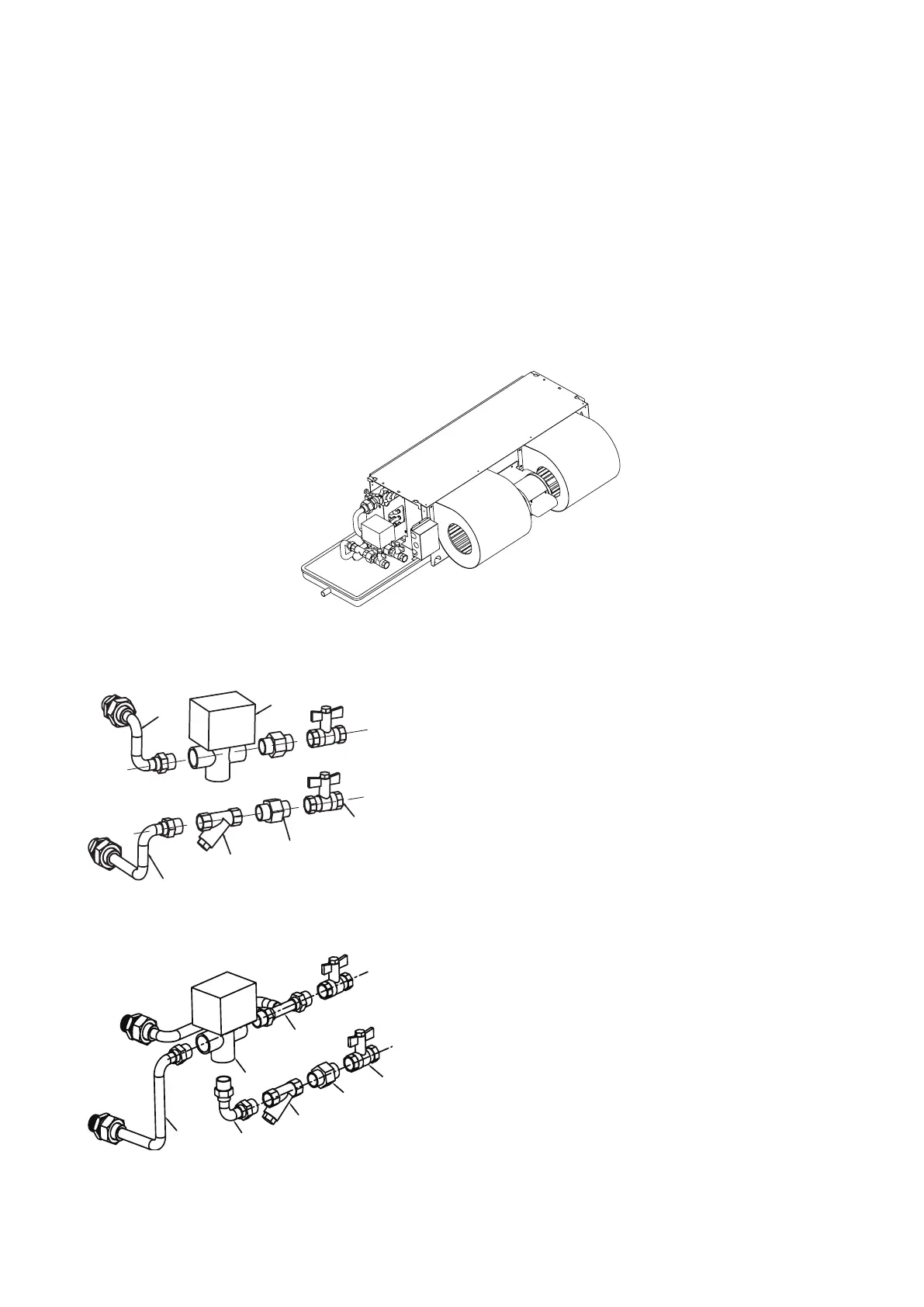
The kit consists of (refer structure gure 0):
• 2/3 way valve body is made of brass, maximum working pressure 1.6MPa.
• Electric actuator has the following specications:
-Power supply: 220V±10%/50/60Hz (±2Hz)
-Activation: ON/OFF
• Hydraulic kit for the installation of the valve on the heat exchanger, complete with 2 ball valves for
adjusting the water ow and for closing the water circuit when perform maintenance to the unit.
• Y-strainer protects unit from impurity, increases the service life and insolating valves.
All parts of 2-way valve kit are indicated in the gure 1. ( For right pipe connection unit.)
All parts of 3-way valve kit are indicated in the gure 2. ( For right pipe connection unit.)
Figure 1
Figure 2
A Ball valve
B Brass connector
C Y-strainer
D Water inlet pipe
E Water outlet pipe
F 2-way valve
A Ball valve
B Brass connector
C Y-strainer
D Connector pipe
E Water inlet pipe
F 3-way valve
G Water outlet pipe
Figure 0


 To Next Page