17
Insulation
1. The insulation design and materials should be complying with local and national codes and regulations.
2. Chilled water pipes and all parts on the pipes should be insulated.
The ow resistance of the connecting valve/hydraulic kit assembly is obtained from the following formula:
△P
W
= (Q
W
/100K
v
)
2
P
W
is the ow resistance (Pa)
Q
W
is the water ow rate (m
3
/h)
K
v
is the ow rate identied in the table
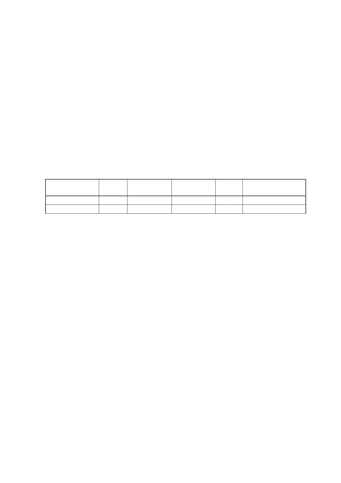
Valve Model DN
Conncetion
Type
Valve Type KV
Shut-off Pressure
Difference (MPa)
MC-FCV3335G 20 Rc3/4" 3-way Valve 3.4 0.18
MC-FCV2334G 20 Rc3/4" 2-way Valve 3.0 0.18
Pipe Connection
1. Using suitable ttings as water pipe connections with reference to the outline and dimensions.
2. The water inlet is on the bottom while outlet on top.
3. The connection must be concealed with rubberized fabric to avoid leakage.
4. Tightening torque should not be too high when connecting water pipes, in order to avoid brass deformation
or water-leakage by torsion split.
Wiring
1. Refer to the wiring diagram of the appropriate controller.
2. For connection with the DAIKIN controller, position the water temperature probe into the appropriate
position. Refer to the dedicated controller installation and operation manual.


 To Next Page