OM 931-6 • MicroTech III Unit Controller for WSHP 25 www.DaikinApplied.com
appendIx C – typICal WIrIng dIagraMs
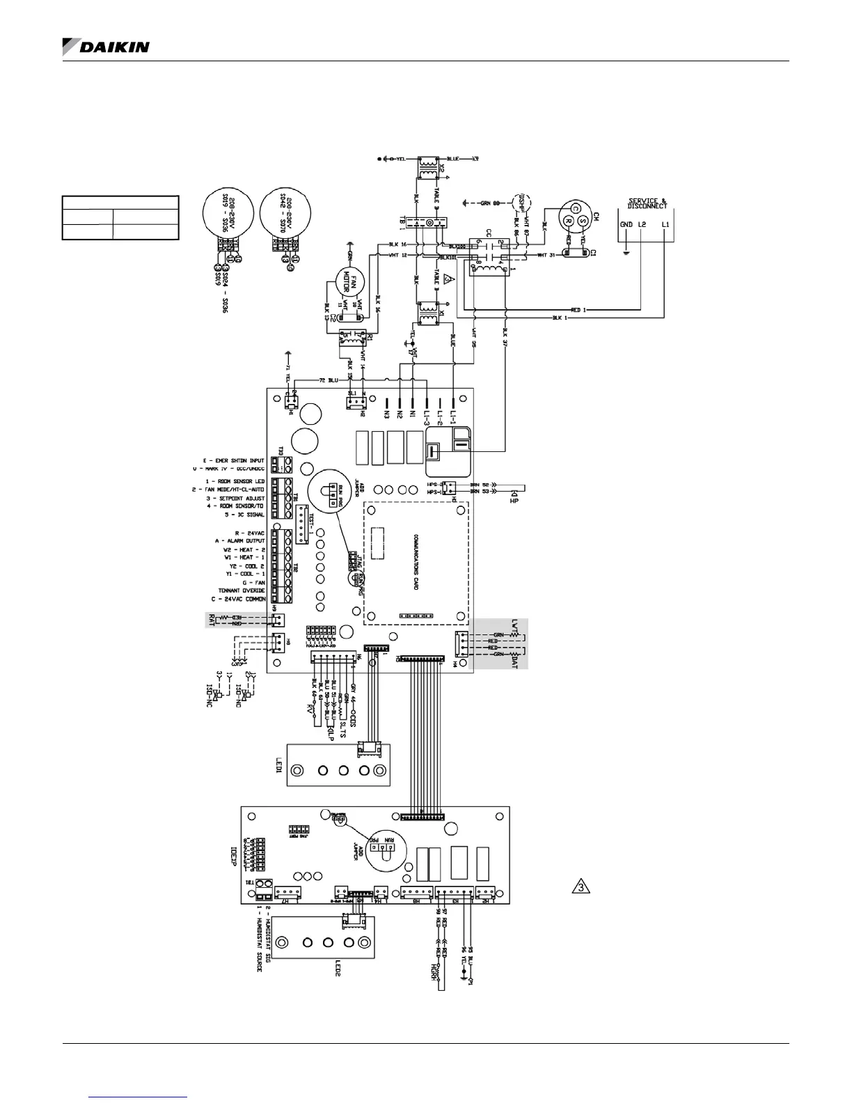
MicroTech III Unit Controller with PSC Motor, Desuperheater and I/O Expansion
Module for Hot Gas Reheat Control (Unit Sizes 019-070) 208/230/60/1-Phase
Drawing No. 669007101A
Wiring diagrams are typical. For the latest drawing
version refer to the wiring diagram located on the inside
of the controls access panel of the unit.
Note: Gray tinted areas in the wiring diagram: Units with factory installed communication module include Discharge Air Temperature (DAT) and
Return Air Temperature (RAT) sensors shipped loose and are field installed. The Leaving Water Temperature (LWT) sensor is factory installed.
Table B
208V RED
230V ORG
Notes:
Transformer:
Unused wire to be capped.
Legend
Item Description
C1 Capacitor-Compressor
C2 Capacitor-Fan
CC Compressor - Contactor
CM Compressor - Motor
COS Condensate Overow Sensor
DAT Discharge Air Temp Sensor
HP High Pressure Switch
HTR Electric Heater Cartridge
IOEXP I/O Expansion Board / Harness
ISO-NC Isolation Valve - Normally Closed
ISO-NO Isolation Valve - Normally Open
DSHP Desuperheater Pump
HGRH 3-Way Valve Solenoid
P1 24 VAC Supply I/O Expansion Brd.
LED1 LED Annunciator / Harness
LED2 LED Annunciator / Harness
LP Low Pressure Switch
SLTS Suction Line Temp Sensor
LWT Leaving Water Temp Sensor
MIII MicroTech III Main Board
R1 Relay - Fan Motor
R2 Relay - Electric Heat
RAT Return Air Temp Sensor
RV Reversing Valve Solenoid
TB1 Power Terminal Block
X1 Primary 24 VAC Transformer
X2 Secondary 24 VAC Transformer
_____
Standard Unit Wiring
_ _ _ _
Optional Wiring (by others)

 Loading...


