OM 931-6 • MicroTech III Unit Controller for WSHP 4 www.DaikinApplied.com
Control Boards Terminals and
Connectors Descriptions
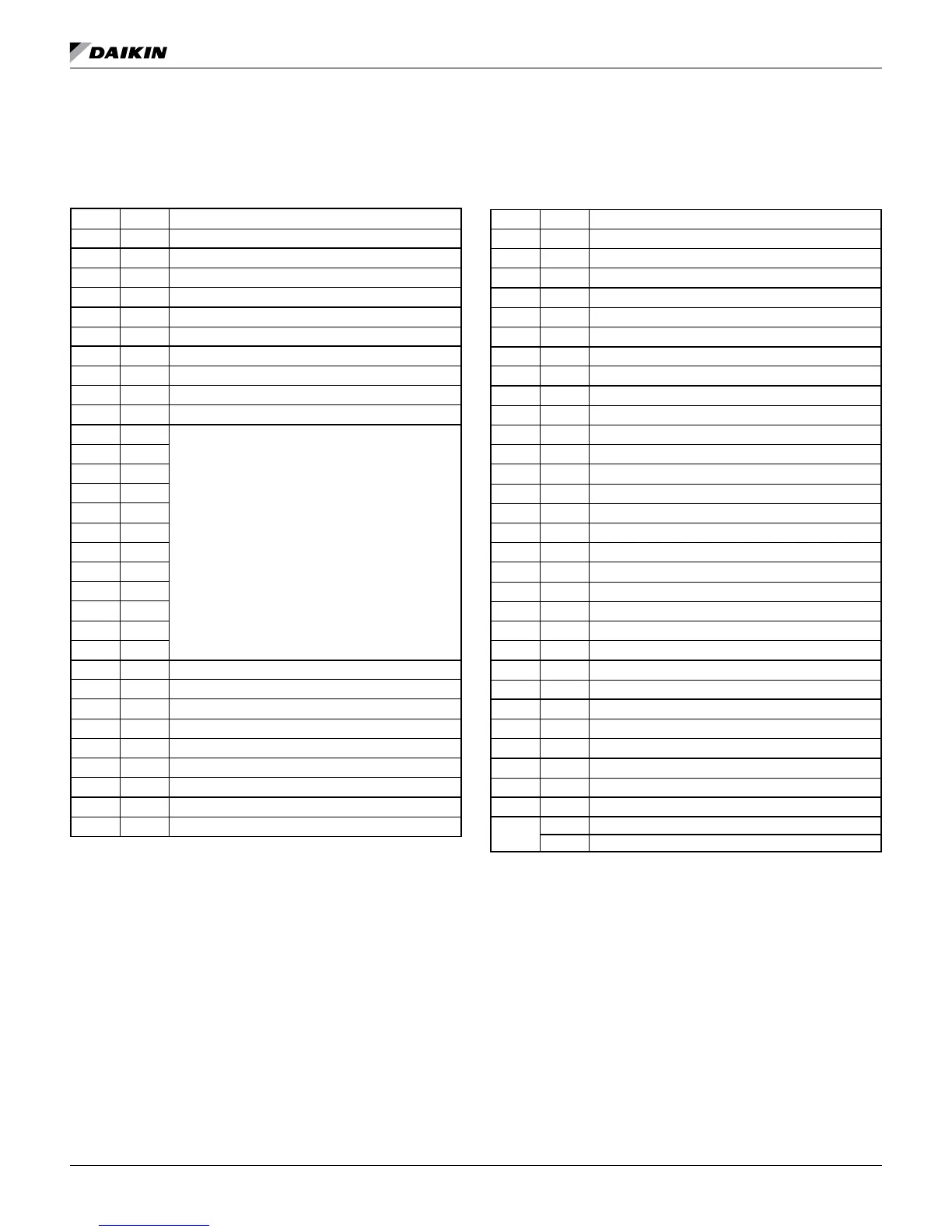
Table 1: MicroTech III Unit Controller Terminals &
Descriptions
H1 – 1 24 24 VAC Power Input
H1 – 2 C 24 VAC common
H2 – 1 SL1 Fan Low Speed Output – Switched L1
H2 – 2 Blank Terminal
H2 – 3 N Fan Low Speed Output – Neutral
H3 – 1 HP1-1 Comp High Pressure Switch (HP1) Input Terminal 1
H3 – 2 HP1-2 Comp High Pressure Switch (HP1) Input Terminal 2
H4 – 1 1 Discharge Air Temp Sensor – Common
H4 – 2 Discharge Air Temp Sensor – Signal
H4 – 3 Leaving Water Temp Sensor – Common
H4 – 4 Leaving Water Temp Sensor – Signal
H5 – 1 1
Connections to I/O Expansion Board
H5 – 2
H5 – 3
H5 – 4
H5 – 5
H5 – 6
H5 – 7
H5 – 8
H5 – 9
H5 – 10
H5 – 11
H5 – 12
H6 – 1 1 Condensate Overow Signal Input
H6 – 2 Compressor Suction Temp Sensor (LT1) – Common
H6 – 3 Compressor Suction Temp Sensor (LT1) – Signal
H6 – 4 Compressor Low Pressure Switch (LP1) – Source Voltage
H6 – 5 Compressor Low Pressure Switch (LP1) – Signal
H6 – 6 Reversing Valve – Common
H6 – 7 Reversing Valve – Output
H7 – 1 1 No Connection
H7 – 2 No Connection
MICroteCh III unIt Controller
H7 – 3 Red LED Output
H7 – 4 Green LED Output
H7 – 5 Yellow LED Output
H7 – 6 Red-Green-Yellow LED Common
H8 – 1 1 Isolation Valve/Pump Request Relay N/O
H8 – 2 Isolation Valve/Pump Request Relay N/C
H8 – 3 24 VAC Common
H9 – 1 1 Room Temp Sensor & Tenant Override – Signal
H9 – 2 Room Temp Sensor & Tenant Override – Common
TB1 – 1 1 Room Sensor – Status LED Output
TB1 – 2 2 Room Sensor – Fan Mode & Unit Mode Switches
TB1 – 3 3 Room Sensor – Setpoint Adjust Potentiometer
TB1 – 4 4 Room Sensor – Room Temp Sensor & Tenant Override
TB1 – 5 5 Room Sensor – DC Signal Common
TB2 – 1 R 24 VAC
TB2 – 2 A Alarm Output
TB2 – 3 W2 Thermostat – Heat Stage #2 (W2) Input
TB2 – 4 W1 Thermostat – Heat Stage #1 (W1) Input
TB2 – 5 Y2 Thermostat – Cool Stage #2 (Y2) Input
TB2 – 6 Y1 Thermostat – Cool Stage #1 (Y1) Input
TB2 – 7 G Thermostat – Fan Input
TB2 – 8 O Thermostat – Tenant Override Input
TB2 – 9 C 24 VAC Common
TB3 – 1 E Emergency Shutdown Input
TB3 – 2 U Unoccupied/Occupied Input
L1 – 1 L1 - 1 Line Voltage Terminal 1
L1 – 2 L1 - 2 Line Voltage Terminal 2
L1 – 3 L1 - 3 Line Voltage Terminal 3
N1 N1 Neutral Terminal 1
N2 N2 Neutral Terminal 2
N3 N3 Neutral Terminal 3
COMP
Relay
SWL1 Switch – L1 Voltage
L1 No Connection

 Loading...


