OM 1239 24 www.DaikinApplied.com
MICroteCh III unIt Controller
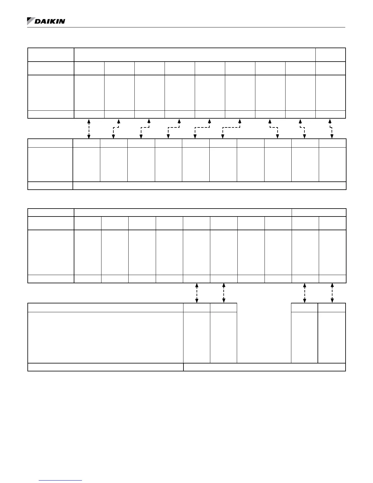
Figure 12: MicroTech III board to digital room temperature sensor wiring
Control Board MicroTech III Board
I/O Expan-
sion Module
Terminal Block
Label
TB2-1 TB1-1 TB1-2 TB1-3 TB1-4 TB1-5 TB3-1 TB3-2 TB1-1
Description
24VAC
Status LED
Output
Fan & Unit
Mode Switches
Setpoint Adjust
Room Temp
Sensor & Ten-
ant Override
DC Signal
Common
Emergency
Shutdown Input
Unoccupied
Input
Humidistat (De-
humidication/
WSE) Signal
Input
Terminal Label R 1 2 3 4 5 E U 1
Typical Wiring
Terminal Label R (24VAC) 1 (ST) 2 (FM) 3 (SP) 4 (UTS) 5 (GND) 6 (FC) E U DH
Description
24VAC
Unit Status
Output
Fan & Unit
Mode
Setpoint Adjust
Room Temp
Sensor & Ten-
ant Override
DC Signal
Common
Fan Speed Se-
lect - Fan Coil
Version Only
Emergency
Shutdown
Unoccupied
Dehumidica-
tion
Sensor Digitally Adjustable Room Temperature Sensor (Part No. 910121754)
Figure 13: MicroTech III board & I/O expansion module to field supplied room temperature sensor wiring
Control Board MicroTech III Unit Control Board I/O Expansion Module
Terminal Block
Label
TB2-1 TB1-1 TB1-2 TB1-3 TB1-4 TB1-5 TB3-1 TB3-2 TB1-1 TB1-2
Description
24VAC
Unit Status Output
Fan & Unit Mode
Setpoint Adjust
Room Temp Sensor
& Tenant Override
DC Signal Common
Emergency Shut-
down Input
Unoccupied Input
Dehumidication
Input
Humidistat Source
Voltage (24VAC)
Terminal Label R 1 2 3 4 5 E U 1
Typical Wiring
Terminal Label X X X X
Description
Room Temp Sensor,
10K Ohm ATP Curve Z
or equivalent
DC Signal Common
Dehumidication Output
Dehumidication
Source Voltage
Sensor Field Supplied Room Temperature Sensor