OM 1239 7 www.DaikinApplied.com
MICroteCh III unIt Controller
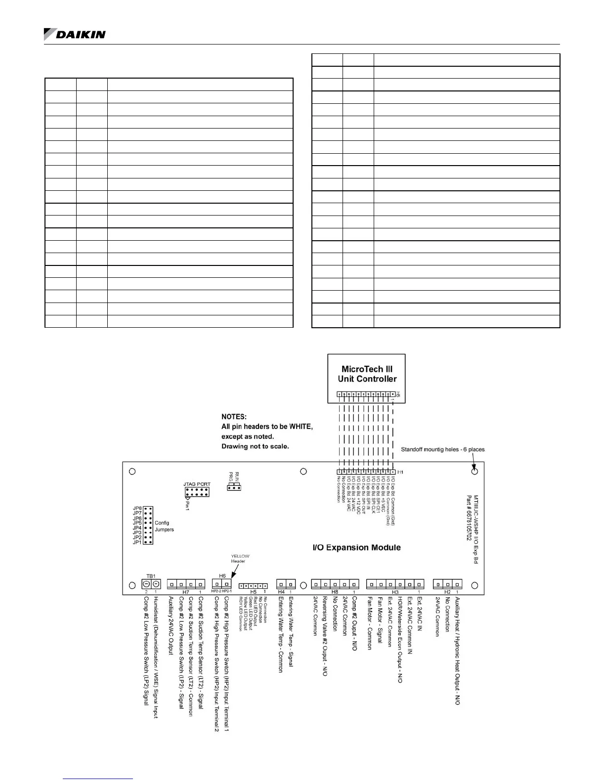
Table 3: I/O expansion module terminals locations and
descriptions
H1 – 1 1 I/O Expansion Board Common (Gnd)
H1 – 2 I/O Expansion Board Common (Gnd)
H1 – 3 I/O Expansion Board +5 VDC
H1 – 4 I/O Expansion Board SPI CE1
H1 – 5 I/O Expansion Board SPI CLK
H1 – 6 I/O Expansion Board SPI IN
H1 – 7 I/O Expansion Board SPI OUT
H1 – 8 1 I/O Expansion Board +12 VDC
H1 – 9 I/O Expansion Board 24 VAC
H1 – 10 I/O Expansion Board 24 VAC
H1 – 11 No Connection
H1 – 12 No Connection
H2 – 1 1 Auxiliary Heat / Hydronic Heat Output – N/O
H2 – 2 No Connection
H2 – 3 24 VAC Common
H3 – 1 1 Ext. 24 VAC In
H3 – 2 Ext. 24 VAC Common In
H3 – 3 HGR / Waterside Economizer Output – N/O
H3 – 4 Ext. 24 VAC Common
H3 – 5 Fan Motor – Signal
H3 – 6 Fan Motor – Common
H4 – 1 1 Entering Water Temp Sensor – Signal
H4 – 2 Entering Water Temp Sensor – Common
H5 – 1 1 No Connection
H5 – 2 No Connection
H5 – 3 Red LED Output
H5 – 4 Green LED Output
H5 – 5 Yellow LED Output
H5 – 6 Red-Green-Yellow LED Common
H6 – 1 HP2-1 Comp #2 High Pressure Switch (HP2) Input Terminal 1
H6 – 2 HP2-2 Comp #2 High Pressure Switch (HP2) Input Terminal 2
H7 – 1 Comp #2 Suction Temp Sensor (LT2) – Signal
H7 – 2 Comp #2 Suction Temp Sensor (LT2) – Common
H7 – 3 Comp #2 Low Pressure Switch (LP2) – Signal
H7 – 4 Auxiliary 24VAC Output
H8 – 1 1 Compressor #2 Output – N/O
H8 – 2 24 VAC Common
H8 – 3 No Connection
H8 – 4 Reversing Valve #2 Output – N/O
H8 – 5 24 VAC Common
TB1 – 1 1 Humidistat (Dehumidication / WSE) Signal Input
TB1 – 2 2 Comp #2 Low Pressure Switch (LP2) – Signal
Figure 2: I/O expansion module terminals locations