IM 1287-6 • REBEL APPLIED ROOFTOP 124 www.DaikinApplied.com
General Gas Furnace Information
This furnace must be installed in the designated non-
combustible heat chamber of the cabinet. If it is removed, it
is only to be replaced with an approved Original Manufacture
Equipment Supplier furnace(s), installed and operated as
specied by the approved Original Manufacture Equipment
Supplier. It is not designed to have any portion of the heat
exchanger outside the cabinet in which the furnace module is
housed.
The Rating Plate/Name Plate has been permanently attached
to the furnace assembly. It contains information including gas
type, maximum and minimum input rating, manifold pressure,
maximum and minimum inlet gas pressure, maximum and
minimum airow requirements, output capacity and electrical
rating for the furnace. The plate also includes model number,
serial number and scan code. This plate is to always remain
attached to the furnace.
This furnace must be applied in accordance with the
requirements of its listing. Louvered openings for combustion
air have been provided in the furnace(s) access door. The air
opening provides unrestricted combustion air to the burners
and is sized such that a minimum free area is maintained. The
minimum free area is dened as 1 in
2
(625 mm
2
) per 4000
BTUH (2.345 kW).The access door provides direct access to
the furnace vestibule where the burners, combustion inducer
fan, ignition controls and ignition safeties are housed. The vent
discharge is sized such that it is equal to or larger than the
discharge area of the combustion exhaust inducer fan. A non-
adjustable High Limit Switch will shut o the gas supply to the
main burners before the outlet air exceeds 250°F (121°C).
The cabinet supply air ow delivery package has been
designed to provide suciently well distributed air ow across
the heat exchanger to limit heat exchanger temperatures to
1330 °F (721°C).
Gas Furnace Manifold Diagrams
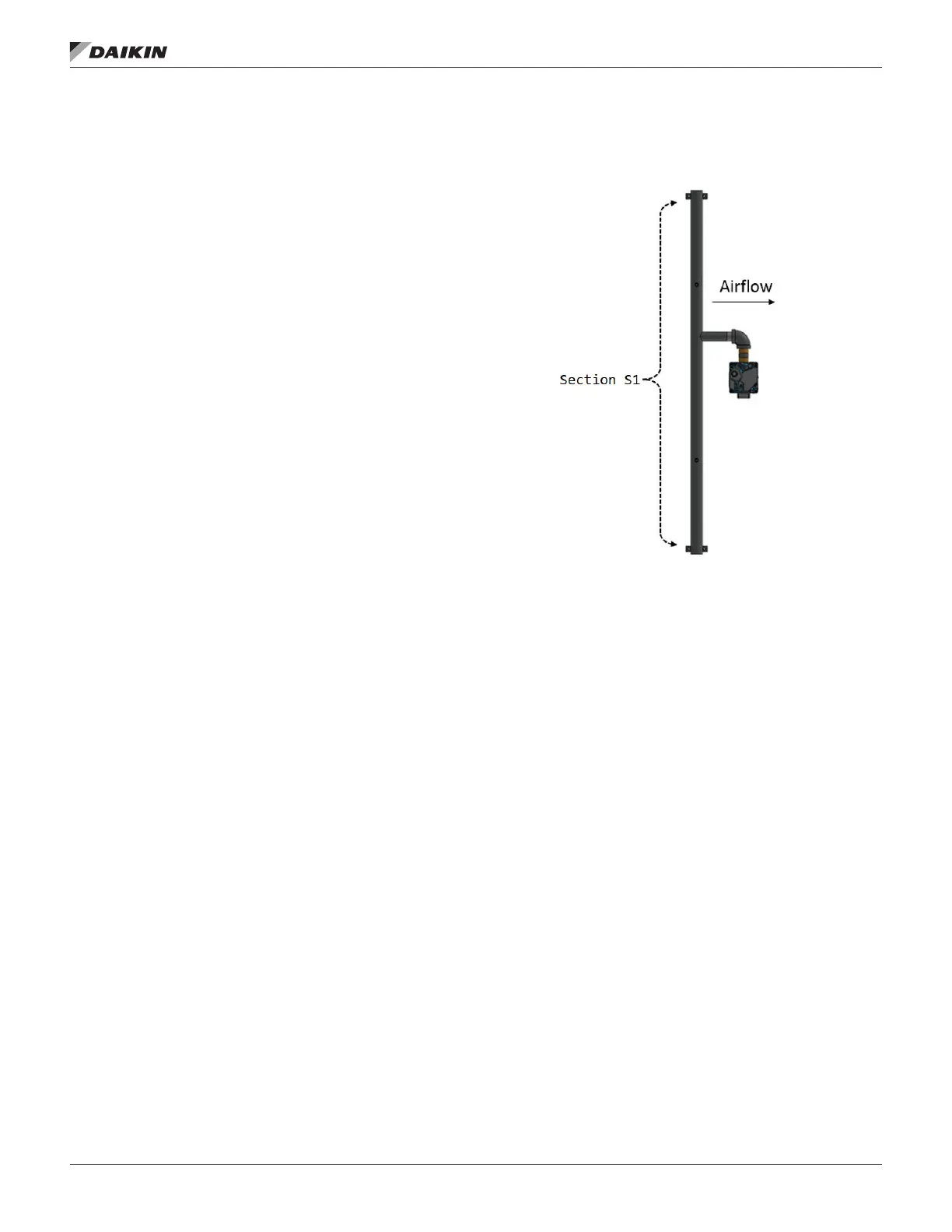
Figure 187: Staged Furnaces – 1 Standard Manifold
NOTE: Includes: 200 MBH (MQ104, MQ104LP), 400 MBH
(MQ108, MQ108LP).
The noted furnaces are congured as one manifold section.
One furnace control board is supplied with this furnace model.
The VB1287 control board controls the staged Section S1 of
the furnace manifold as shown in Figure 187.


 To Next Page