EasyManua.ls Logo

Daikin Rebel Applied DPSA - Controlled Component Locations

Daikin Rebel Applied DPSA
180 pages
Print Icon
To Next Page IconTo Next Page
To Previous Page IconTo Previous Page
Loading...
IM 1287-6 • REBEL APPLIED ROOFTOP 20 www.DaikinApplied.com

Controlled Component Locations
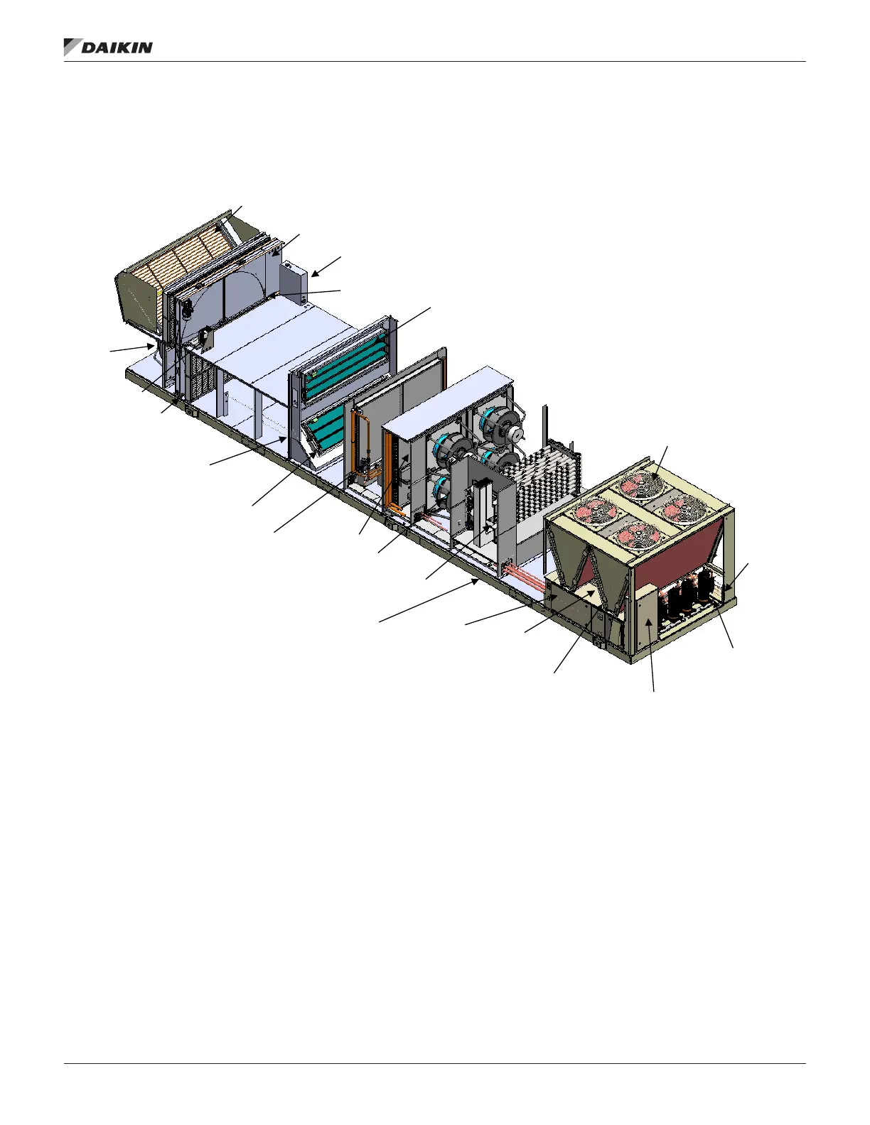
Figure 25 shows basic control and component locations within a typical unit
Figure 25: Typical Control and Component Locations
Return Air Dampers
(Economizer Dampers)
Energy
Recovery VFD
Exhaust
Fans
Outdoor Temp
and/or humidity
Return Temp
And/Or Humidity
Sensors
Supply Fans
Condenser
Fans
Outside Air
Damper
Refrigerant Pressure
Sensors/Switches
Furnace
Low
Voltage
Control
Box
(MT4)
Leaving Coil
Temperature
Energy Wheel
Control Box
Hot Water Coil
Valve
Furnace
Controller
Discharge Air
Temp. (DAT)
Service
ports
Energy Wheel
Outdoor Air Pre Heater
Exhaust Wheel
Temperature
Sensor
Leaving Wheel
Temp. Sensor
Condenser Discharge Air Temp.
Sensor (Field Installed)