IM 1287-6 • REBEL APPLIED ROOFTOP 70 www.DaikinApplied.com
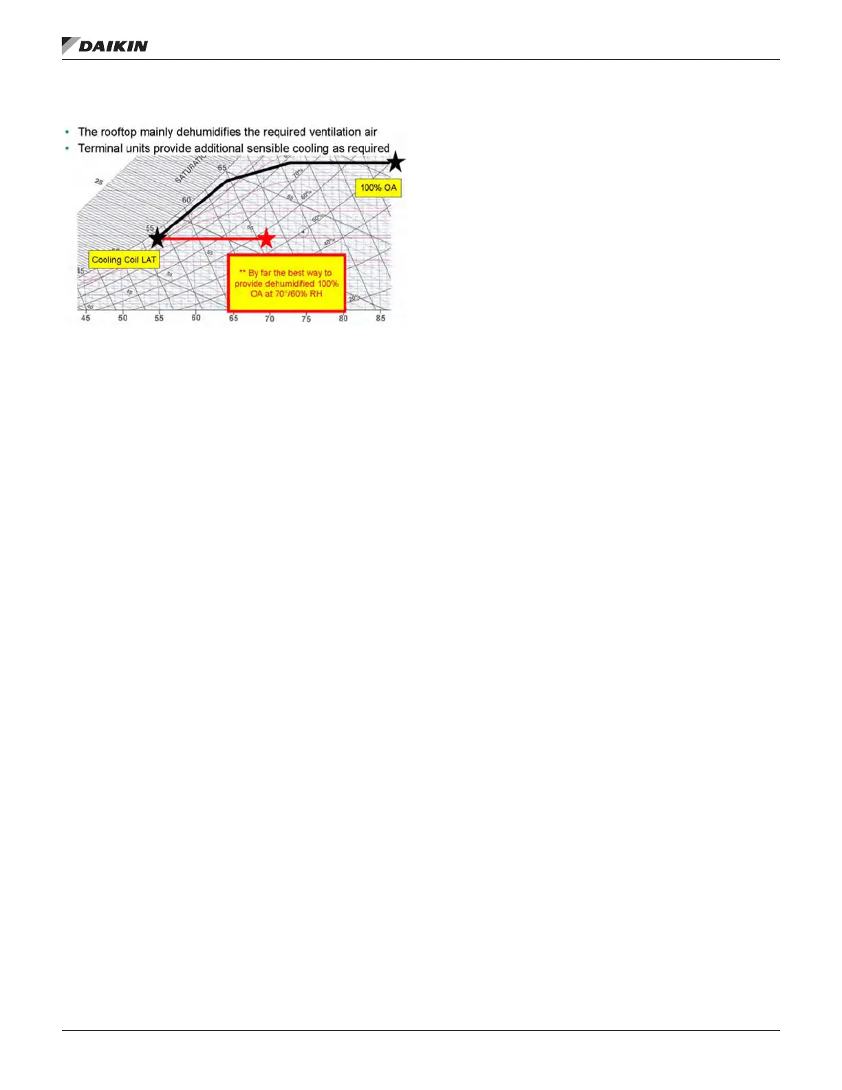
Figure 140: Ideal for Neutral Air Ventilation Control
Modulating Hot Gas Reheat (MHGRH)
Modulating hot gas reheat (MHGRH) systems redirect a
portion of the hot refrigerant coming from the compressor(s) on
circuit 1 to a coil within the airstream. When there is a call for
dehumidication and MHGRH is activated, the compressor(s)
on circuit 1 will rst be utilized to meet the cooling and
dehumidication demand. If the cooling demand cannot
be satised using only the compressor(s) on circuit 1, the
compressors on circuit 2 will be staged to satisfy the remaining
demand.
Modulating Liquid Subcool/Hot Gas Reheat
(MLSCRH+MHGRH)
Modulating liquid subcool reheat (MLSCRH) systems redirect a
portion of the warm liquid refrigerant leaving the condenser coil
on both circuits to a reheat coil within the airstream as shown
in Figure 8 and Figure 9. Due to the increased subcooling
eect with this option, MLSCRH can increase the unit gross
capacity up to 20% depending on operating conditions. When
there is a call for dehumidication and MLSCRH is active,
the compressors will stage/modulate accordingly to meet the
leaving dx coil temperature setpoint and modulate refrigerant
to the liquid reheat coil to meet the leaving unit temperature
(DAT) setpoint. If the DAT setpoint cannot be satised by
MLSCRH only, MHGRH will then be activated to assist in
meeting the DAT setpoint.
Dehumidication Initiation
An analog sensor is mounted in the return duct, the space, or
outdoors to sense Relative Humidity. The location is selected
by setting the Sensor Location value on the keypad to Return,
Space, or OAT. OAT can only be selected for units with DAT
control. Dehumidication is disabled when the unit is in either
the Heating or Minimum DAT state. When Dehumidication is
enabled, Dehumidication operation is initiated when Humidity
Control is set to either Relative Humidity or Dew Point and
that value rises above the appropriate setpoint by more than
half its dead band. Economizer operation is disabled in the
Dehumidication mode, so the unit immediately transitions to
Cooling if Dehumidication is initiated in Economizer state.
Dehumidication Termination
Dehumidication is terminated if the selected variable, Relative
Humidity or Dew Point, drops below the appropriate humidity
setpoint by more than half its dead band. Dehumidication is
also terminated if cooling is disabled for any reason or the unit
enters either the Heating or Minimum DAT state. For units with
compressors, the number of cooling stages is reduced by one
and control reverts to normal control when dehumidication
is terminated in the Cooling state. Another compressor stage
change could then occur after one Cooling Stage Time has
elapsed.
MHGRH Control & Arrangement
In conjunction with dehumidication, MHGRH is used to
raise the temperature of the cooled air to a desirable value
without auxiliary heat. MHGRH is comprised of a parallel coil
arrangement, with both the condenser and reheat coils of
the micro channel type, three-way modulating reheat valve
and dual check valves. MHGRH components will always be
installed in circuit #1.
During Dehumidication control with modulating Hot Gas
Reheat (MHGRH) is done via Modbus signal from the main unit
controller as described below.
• A PI Loop is used to control the MHGRH valve to
maintain the Discharge Air Temperature from the reheat
coil.
• Compressor staging during reheat (or dehumidication)
will be controlled by the Leaving DX Coil Temperature.
For increased dehumidication during reheat, the
standard default compressor staging range is 45 - 52°F.
• When dehumidication is active in the Cooling state, the
reheat set point equals the DAT Cooling Setpoint. For
DAT units, this is the normal DAT set point resulting from
any reset. For Zone Control units, this set point is the
result of a PI Loop based on the Control Temperature.
• Communication with the reheat control valve is
accomplished by providing a Modbus signal to control the
reheat valve (stepper type).
• In the Fan Only state, no sensible cooling is required, but
the dehumidication mode will still be enabled if the dew
point or humidity sensor is not satised. In this case the
reheat set point varies from a maximum value (default
65°F) when the Control Temperature is at or below the
heating changeover setpoint to a minimum value (default
55°F) when the Control Temperature is at or above the
cooling changeover setpoint.
• Lead/Load Arrangement with MHGRH
— When MHGRH is active, circuit #1 will lead and load
up before starting circuit #2.
— For reheat operation, compressor(s) in circuit #1 must
be active. If the unit is operating in the cooling mode
when a call for dehumidication/reheat arises, circuit #1
will become the lead and the controller will bring on one
additional stage of cooling for dehumidication. If any
compressors in circuit #2 are operating at this moment
they will be switched over to compressors in circuit #1.


 To Next Page
 Loading...