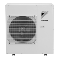
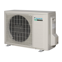
This document is a service manual detailing the removal procedure for Daikin outdoor units in the 6.0/7.0/7.1/8.0/8.5/9.0 kW Class (33000 Btu/h Class). It covers both Cooling Only and Heat Pump models, including specific model numbers such as RKM33NV2S, RKS33JV2S, RKS85HVM, RKS85JVMG, RKS70MVLT, RKS80MVLT, RKS90MVLT for Cooling Only, and RXM71NVLT, RXM80NVLT, RXM90NVLT, RXS60KBVMA, RXS70MVLT, RXS80MVLT, RXS90MVLT for Heat Pump models. The manual emphasizes safety warnings, particularly the need to wait at least 10 minutes after turning off all power supplies before beginning any disassembly work. Illustrations in the manual are primarily based on heat pump models and may vary slightly depending on the specific unit.
Function Description:
This service manual provides a step-by-step guide for disassembling various components of Daikin outdoor units. The primary function of this document is to facilitate maintenance, repair, and replacement of internal parts by outlining the correct and safe removal procedures. It covers the removal of outer panels, the electrical box, PCBs (Printed Circuit Boards), the fan motor, coils/thermistors, sound blankets, and the compressor. Each section details the specific screws, hooks, clamps, and connectors that need to be detached, ensuring technicians can systematically access and remove components. The manual also includes important reassembly notes, such as aligning specific marks on the outdoor fan and motor shaft, and correctly inserting clamps and fixtures.
Important Technical Specifications (Implied by Removal Procedures):
While the manual doesn't list explicit technical specifications like power ratings or dimensions, it implicitly reveals aspects of the unit's construction and internal layout.
- Panel Design: The outdoor unit features multiple outer panels, including a suction grille, top panel, right side panel, front panel (divided into two sections), and a rear panel. These are secured by various screws and hooks, indicating a modular design for accessibility.
- Electrical System: The electrical box houses PCBs, a terminal block, and various wiring harnesses (fan motor, electronic expansion valve coil, four-way valve coil, thermistor ASSY, connecting wire, power supply wire, earth/ground wires). This highlights the complexity and interconnectedness of the electrical components.
- Fan Motor: The fan motor is secured by screws and its lead wire is clamped. The manual specifies an M8 nut for the outdoor fan, indicating a standard fastening mechanism. A D-cut section on the motor shaft and a corresponding mark on the fan are crucial for correct reassembly.
- Coils/Thermistors: The unit incorporates an electronic expansion valve coil, an outdoor heat exchanger thermistor, and a discharge pipe thermistor. These components are critical for refrigerant control and temperature sensing. The thermistors are secured with clips and harnesses, emphasizing their precise placement.
- Compressor: The compressor is a central component, connected by lead wires (U, V, W) and protected by an overload protector (OL). Its piping is brazed, requiring specialized tools and safety precautions for removal. The compressor is secured by nuts, indicating a robust mounting system.
- Sound Insulation: Sound blankets are used for noise reduction, covering the compressor and other internal components. These are described as fragile and require careful handling during removal and reassembly.
- Heat Exchanger: The presence of an auxiliary heat exchanger in some models is noted, indicating variations in unit configurations.
Usage Features (for Technicians):
- Step-by-Step Instructions: The manual provides clear, numbered steps for each removal procedure, making it easy for technicians to follow.
- Visual Aids: Each step is accompanied by detailed illustrations, showing the exact location of screws, hooks, clamps, and components, which significantly aids in understanding and execution.
- Points/Notes for Clarity: "Points" sections offer additional information, warnings, and tips, such as the location of hooks, specific nut sizes, reassembly alignment instructions, and model-specific variations (e.g., cooling-only models lacking certain harnesses).
- Safety Warnings: Prominent "Warning" and "Caution" sections highlight critical safety considerations, including waiting times after power-off, risks of burns, refrigerant leakage, fire hazards, and proper handling of tools and materials.
- Tool Guidance: Implicitly, the manual guides technicians on the types of tools needed (e.g., screwdrivers, pliers, tube cutter, brazing machine).
- Environment Protection: The manual explicitly states the importance of not discharging refrigerant gas into the atmosphere, emphasizing environmentally responsible practices.
- Troubleshooting/Repair Facilitation: By detailing component removal, the manual enables technicians to isolate and replace faulty parts, thereby facilitating repair and maintenance.
Maintenance Features (for Technicians):
- Systematic Disassembly: The manual promotes a systematic approach to disassembly, reducing the risk of damage to components and ensuring efficient reassembly.
- Component Identification: Clear labeling of parts (e.g., [S20], [S80], [S90] for connectors, [HR1], [HR2] for reactor harnesses) helps technicians identify and manage components during maintenance.
- Reassembly Guidance: Instructions for reassembly are integrated into the "Points" sections, ensuring that components are put back correctly, such as aligning the outdoor fan with the motor shaft or inserting clamps into designated holes.
- Special Handling Instructions: Specific warnings about fragile components (sound blankets) and sensitive procedures (brazing, handling thermistors) ensure proper care during maintenance.
- Pre-Maintenance Checks: The manual advises ensuring the refrigerant gas is empty in the circuit before working on the compressor, which is a crucial pre-maintenance step.
- Non-Oxidation Brazing: For piping restoration, the manual specifies non-oxidation brazing, indicating a requirement for specific techniques and materials to maintain system integrity.
- Nitrogen Replacement: The instruction to apply nitrogen replacement when heating up brazed parts is a key maintenance practice to prevent oxidation and ensure clean joints.
- Documentation of Changes: The "Revision History" section indicates that the manual is regularly updated with model additions and corrections, ensuring that technicians always have access to the most current and accurate information. This is vital for maintaining a wide range of Daikin units.