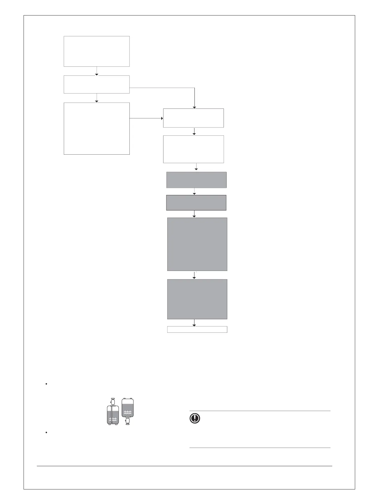
14.3 Method for adding refrigerant
14.3.1 Flow chart
N
Step 1
Step 3
2SQORLOGSLSLQL
OLTLGRSO
(FSFLQPRQ
N
OROLQRGGLLRQO
6ROGE“
LQFQEFG
Step 2
R≤4kg
Step 4
Step 5
RPLFLQF
SRFG
%RFSFLLGPRQRLQLQOLTLG
6LQFLLQLPLGLQGGLQLLQ
FLQFRPSRLLRQRFQSQLQQRPO
RSLRQ
Beforecharging,checkwhethertherefrigerantcylinderis
equippedwithasiphontubeornot.
BesuretousetoolsexclusivelyforR410Atoensurerequired
SLQFQGRSQRLQPLORPPLLQ
6LRFLRQRO RPRLQRPLRQRLQLFS
T
w
S
S
T
w
SGRw
SR
%6
888
%6RPRQ
t01
S
T
t02
SFRQRO
t03
”waitingforstablecooling)
PushBS2within5minutes
t03
2SQO
Displayshow“
t03
”andlow
pressurevalvewithanintervalof
Refrigerantwillbecharged
pe
p9
25
P(kg)wasaddedduring
5
ORO
%6ROSRP
LQLLQLG
)LOOLQPRQRQ
OEO
RRQ
RSLRQ
)LQLG
NOTICE
Chargingwithanunsuitablesubstancemaycauseexplosions
andaccidents,soalwaysmakesurethattheappropriate
refrigerant(R410A)ischarged.Refrigerantcontainersmust
beopenedslowly.