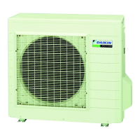
Do you have a question about the Daikin RXS71FAV1B8 and is the answer not in the manual?
Details the various functions available for the air conditioner units.
Lists and describes functions specific to cooling-only operation modes.
Explains the role and function of thermistors in system control.
Presents detailed performance and physical specifications for cooling-only models.
Presents detailed performance and physical specifications for heat pump models.
Shows the wiring connections and component layout for the indoor unit PCB.
Shows the wiring connections and component layout for the outdoor unit PCB.
Explains core operational features like temperature and airflow control.
Details the inverter's frequency control mechanism for capacity adjustment.
Lists and describes common malfunctions and error codes for the system.
Describes the remote controller's buttons, display, and operational modes.
Provides a systematic guide to diagnosing and resolving unit issues.
Lists all error codes with their meanings, symptoms, and solutions.
Guides through the process of verifying unit functionality after installation.
Explains the purpose and configuration of internal jumpers and switches.
Illustrates the refrigerant flow paths within the system.
Shows the electrical connections for various unit components.
| Brand | Daikin |
|---|---|
| Model | RXS71FAV1B8 |
| Category | Air Conditioner |
| Language | English |


