Si-71A For FHYC71K
Removal Procedure 137
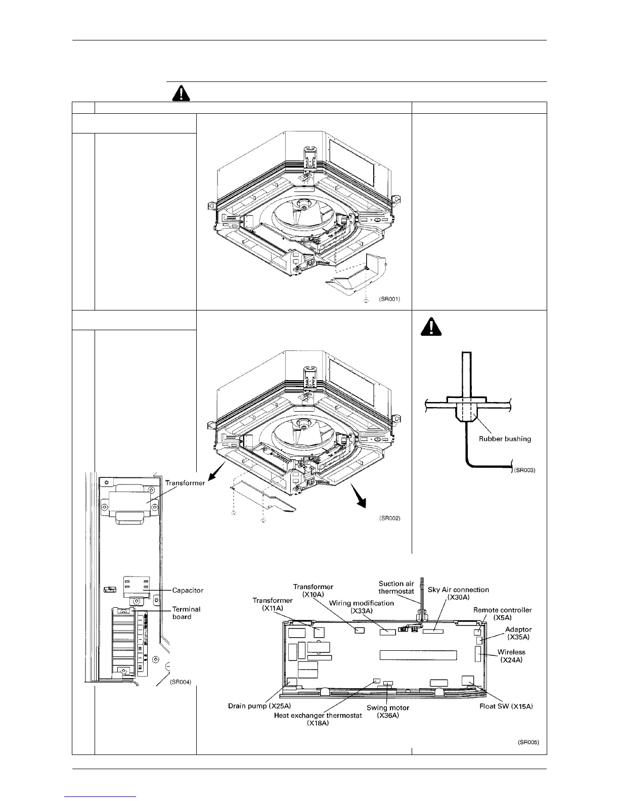
1.9 Removal of Switch Box Cover
Procedure
Warning Be sure to turn off all power supplies before disassembling work.
Step Procedure Points
1. Removing the cover from the
control PCB side
1 Loosen the 1 screw, and pull
the cover toward the inside
and pull it down.
2. Removing the cover from the
connection wire side
Caution
∗
Caution during installation
Set the thermistor base securely on
the rubber bushing.
1 Remove 1 screw and loosen
the other screw. Pull the
cover toward the pipe, then
pull it down
.