SiBE121021_C Outdoor Unit - 50~75 Class
Removal Procedure 375
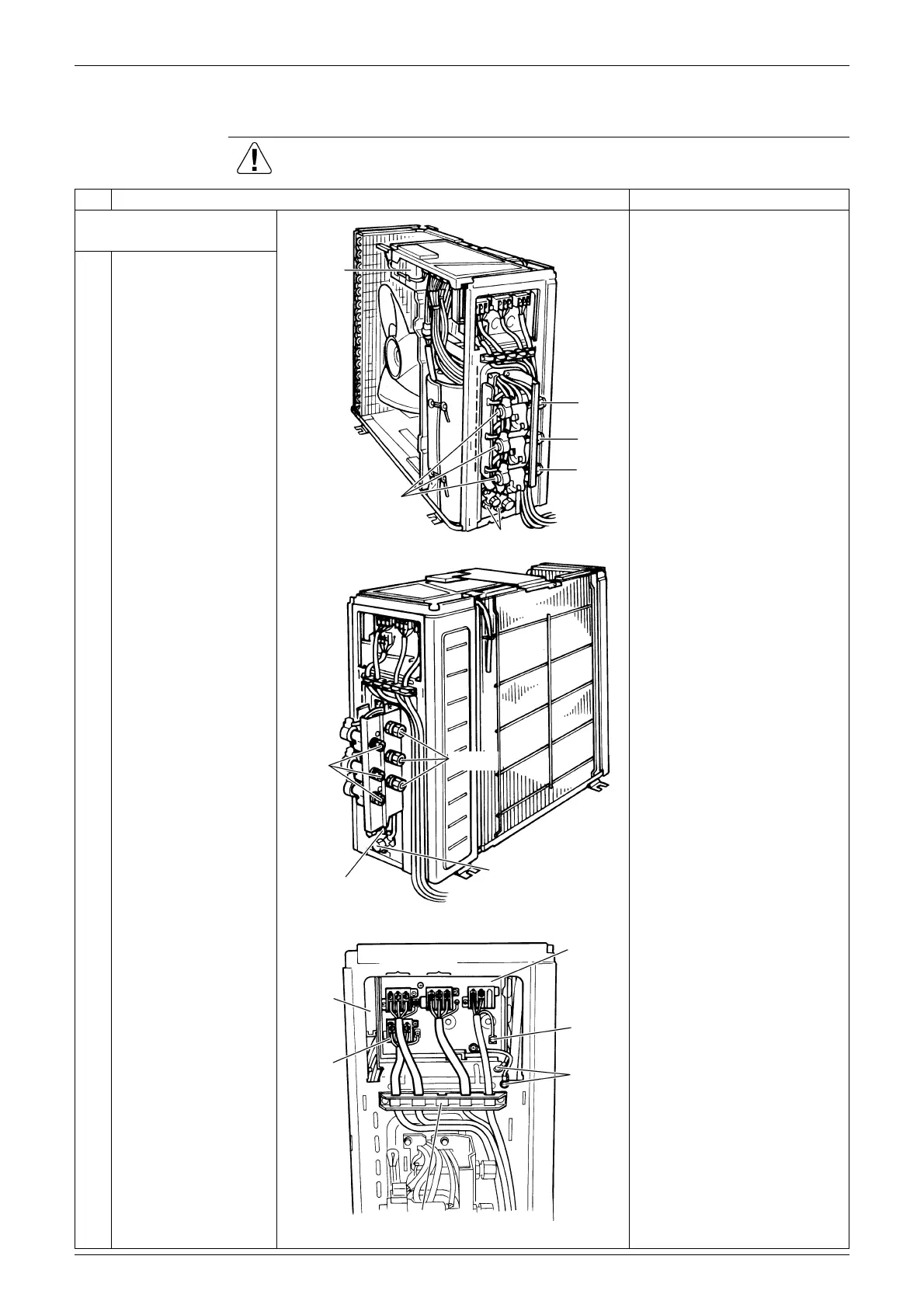
1.2 Removal of Electrical Box
Procedure Warning Be sure to wait for 10 minutes or more after turning off all power
supplies before disassembling work.
Step
Procedure Points
1. Disconnect the
harnesses.
Illustrations are for 3 room
models as representative, 4
room models also have D
port.
1
Layout of the
connecting wires
Connecting wires
(1) Black : Power supply
(2) White : Power supply
(3) Red : Transmission
Power Supply wires
(L) - Black
(N) - White
The wires are fixed to the
terminal board with screws.
Electrical
box
Electronic expansion
valve coil
Service port
A port
B port
C port
(R11175)
Liquid
pipe
Liquid stop valve
Gas stop valve
Gas pipe
(R11176)
(R11177)
Wiring fixture
C port
A port
B port
Service
monitor
PCB
Terminal
board
Earth
wires
Earth
 Loading...