Do you have a question about the Daikin SWP Series and is the answer not in the manual?
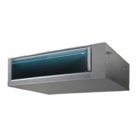
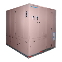
Details Daikin Applied's self-contained air conditioning units, model SWP, and their key components.
Covers initial steps for unit installation, including inspection, handling, and vibration isolators.
Procedure for disassembling and reassembling modular units, including section identification.
Step-by-step guide for reassembling the unit sections after disassembly.
Tables detailing physical specifications, model sizes, and refrigerant charges for SWP units.
General guidelines for field wiring, complying with codes, and using appropriate materials.
Overview of the control center, its compartments, and the high and low voltage components.
Details on Manual Motor Protectors (MMPs) and Circuit Breakers, including functions and reset.
Reference to Table 10 for the electrical legend and its standard locations.
Diagram showing the main power connections for variable volume systems.
Diagram illustrating the control input connections for variable volume systems.
General procedures and warnings for starting up the unit, including pre-start checks.
Steps for starting the supply air fan and compressors, including safety checks.
Guidelines for charging refrigerant, including preferred methods and acceptable oils.
Routine maintenance tasks to avoid expenses and ensure system longevity.
Information on compressor warranty, ordering replacements, and failure analysis.
A form for documenting initial checks and start-up procedures for warranty registration.
| Brand | Daikin |
|---|---|
| Model | SWP Series |
| Category | Air Conditioner |
| Language | English |