InsTallaTIon
www.DaikinApplied.com 9 IM 1137-4 • TEMPLIFIER
®
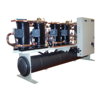
MODEL TGZ
Chilled Water Piping
CAUTION
To prevent damage to the evaporator and potential chiller
failure, a supply strainer is required in the inlet water piping
which connects to this evaporator. This strainer must be
installed prior to operation of the chilled liquid pumps.
NOTE: Since the Templier evaporator and/or condenser
may have to be valved off for cleaning or repair, it
may be desirable to pipe a bypass around them
so that system source and hot water ow is not
interrupted.
Field installed water piping to the chiller must include:
• A cleanable strainer installed at the water inlet to the
evaporator to remove debris and impurities before they
reach the evaporator. Install cleanable strainer within
5 feet (1500 mm) of pipe length from the evaporator
inlet connection and downstream of any welded
connections (no welded connections between strainer
and evaporator).
• TGZ models require a strainer with perforations no larger
than 0.062” (1.6 mm) diameter. See the Inlet Strainer
Guidelines on Table 2 on page 11 for more information.
• A water ow switch must be installed in the horizontal
piping of the supply (evaporator outlet) water line to avoid
evaporator freeze-up under low or no ow conditions. The
ow switch may be ordered as a factory-installed option,
a eld-installed kit, or may be supplied and installed in the
eld.
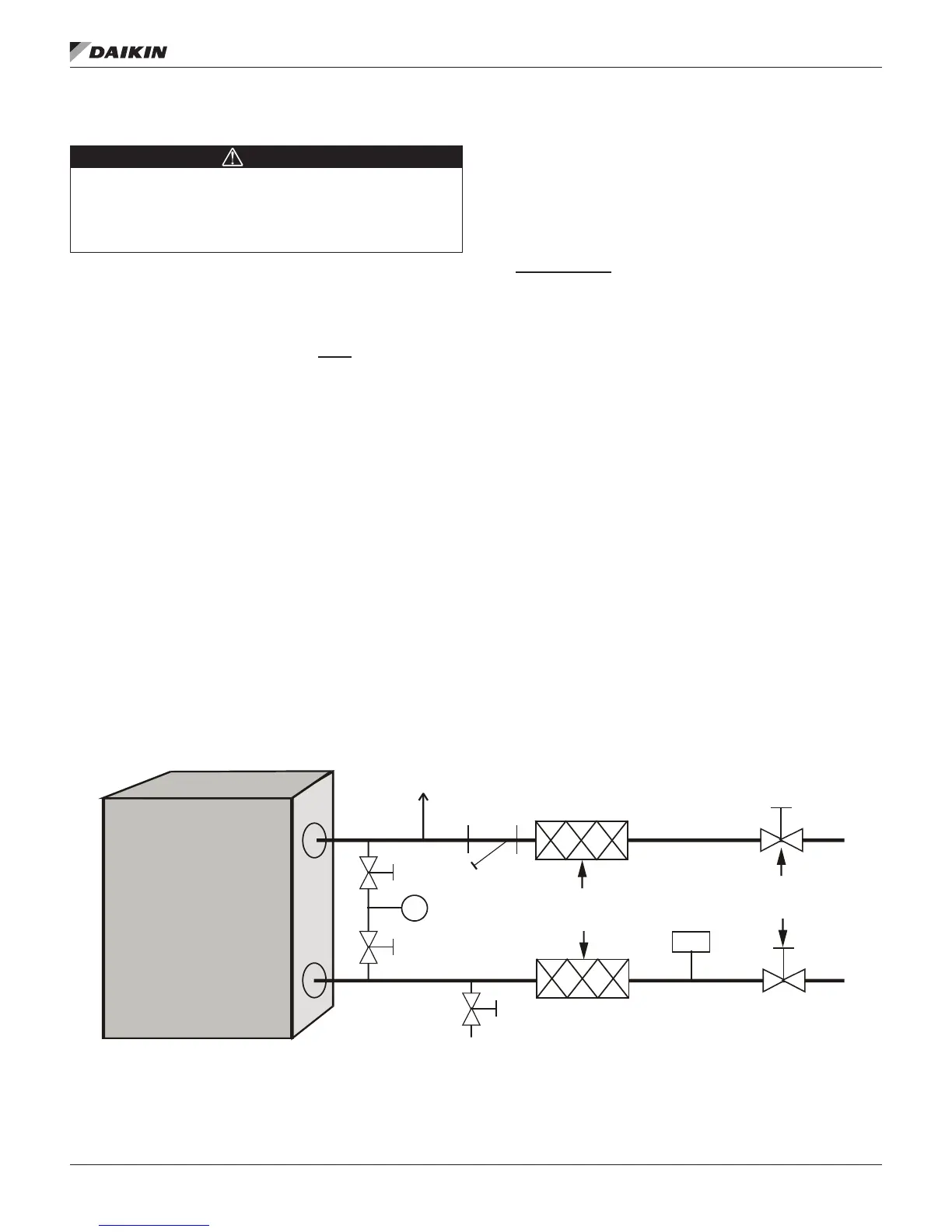
• Piping for units with brazed-plate evaporators must have
a drain and vent connection provided in the bottom of
the lower connection pipe and to the top of the upper
connection pipe, respectively. See Figure 7. These
evaporators do not have drain or vent connections due to
their construction.
• Purge air from the water system before unit start-up to
provide adequate ow through the evaporator.
• Adequate piping support, independent from the unit,
to eliminate weight and strain on the ttings and
connections.
It is recommended that the eld installed water piping to the
chiller include:
• Thermometers at the inlet and outlet connections of the
evaporator.
• Water pressure gauge connection taps and gauges at
the inlet and outlet connections of the evaporator for
measuring water pressure drop.
• Shutoff valves are necessary to isolate the unit from the
piping during unit servicing.
• Minimum bends and changes in elevation to minimize
pressure drop.
• An expansion tank and regulating valve to maintain
adequate water pressure. Tank becomes required
for closed loop systems based on water volume and
temperature ranges.
• Vibration eliminators in both the supply and return water
lines to reduce transmissions to the building.
• Flush the system water piping thoroughly before making
connections to the unit evaporator.
• Piping insulation, including a vapor barrier, helps prevent
condensation and reduces heat loss.
• Regular water analysis and chemical water treatment
for the evaporator loop is recommended immediately at
equipment start-up.
Figure 7: Typical Piping for Brazed-Plate Evaporator
Air
Vent
Flow
Switch
Vibration
Eliminators
Drain
Outlet
Inlet
P
Isolation
Valves
Strainer
WELDED PIPE CONNECTIONS ARE NOT ALLOWED
BETWEEN THE STRAINER AND EVAPORATOR DUE
TO THE CHANCE OF SLAG ENTERING THE EVAPORATOR
 Loading...