34
Control System Instruction
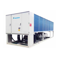
Power Cable Connection Diagram
R TS TR S
L2
L3
S
R T
PE
Master unit
N# Slave unit
Breaker with a
current leakage
protector
Breaker with a
current leakage
protector
Breaker with a
current leakage
protector
380V/3Ph/60Hz
0#Slave unit
L1
460V/3Ph/60Hz
■ The dimension of power cable connection refer to electical parameters.
■ All wires must be securely connected.
■ Wires must not contact the refrigerating pipes or moving parts of the compressor and the fan.
■ N≤9
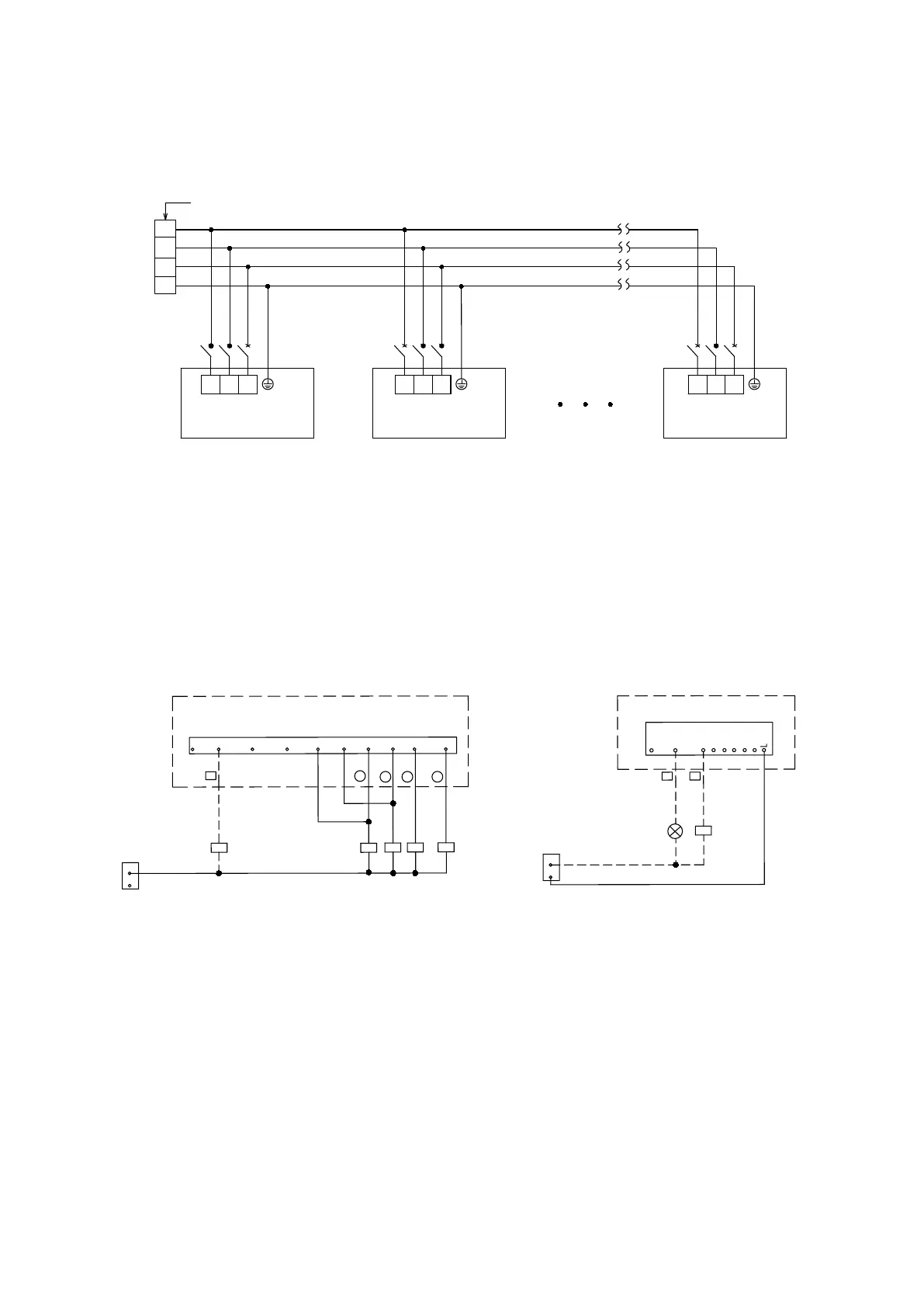
PCB instruction
Connection illustration for the pump and the auxiliary heat exchanger
NOTE: ------- PARTS WITHIN THE DASHED BOX ARE TO BE CONNECTED ONSITE. THE OUTPUT VOLTAGE OF THE MODULE
INTERFACE IS 220-240 V.
——PARTS WITHIN THE REAL-LINE BOX ARE CONNECTED BEFORE DELIVERY.
A COOLING ONLY UNIT HAS NO 4WV1 AND 4WV2 OUTPUT. A SLAVE UNIT HAS NO EXTENSION BOARD UAL-E.
HEAT—BPHE ELECTRIC HEATER ;PUMP—WATER PUMP ;4WV—4-WAY VALVE ;FANL—FAN AT LOW SPEED; FANH—FAN AT HIGH
SPEED; COMP—COMPRESSOR; WHEAT—AUXILIARY ELECTRIC HEATER OF THE WATER SYSTEM ;W-TWV—2-WAY VALVE
INTERLOCK OF THE WATER SYSTEM
HEAT
PUMP
4WV2
4WV1
FANL1
FANL2
FANH1
FANH2
COMP2
COMP1
Pump connection illustration
Auxiliary heat exchanger connection illustration
N
L
KM5
KM4
KM3
KM2
KM1
N
L
KM1
WHEAT
ALARM
W-TWV
ALARM INDICATOR
2
39
7 15 16
36
3