32
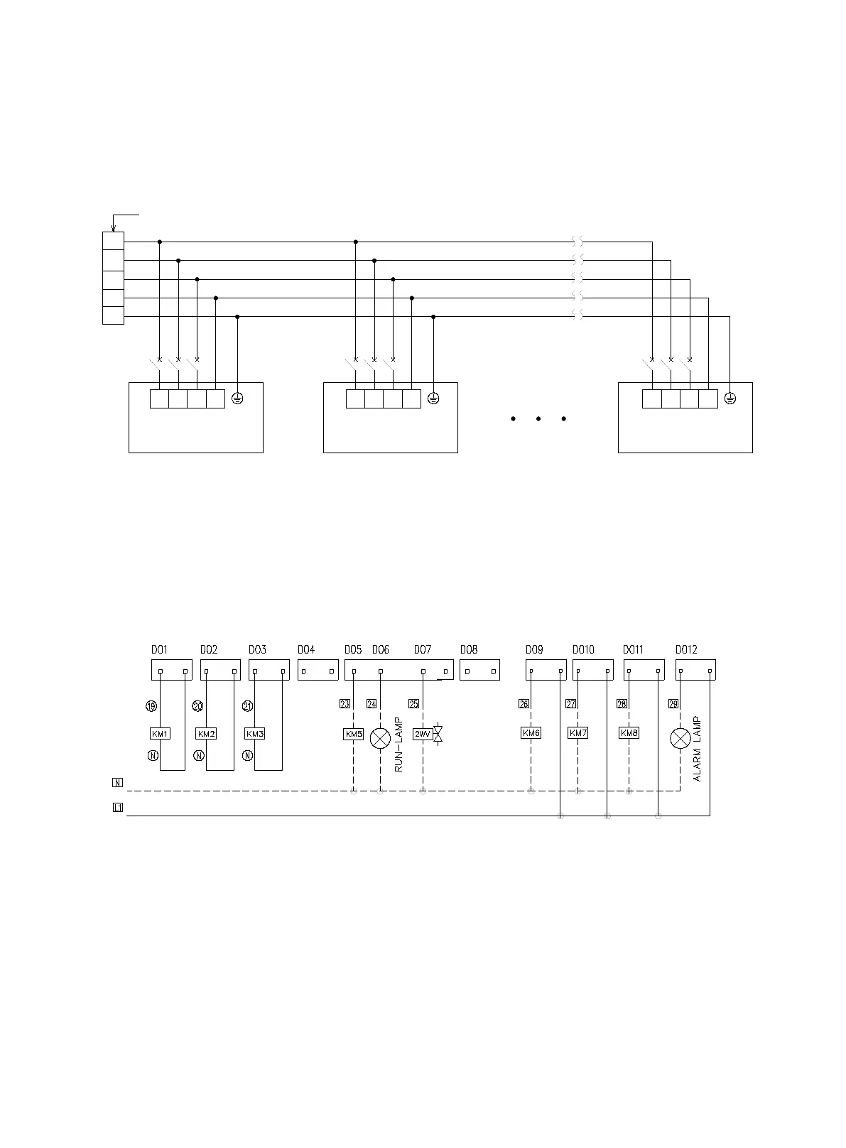
Power Cable Connection Diagram
PCB instruction
Control System Instruction
N
R
T NS T N
R
S
L1
L2
L3
NS
R
T
380V/3N~/50Hz
PE
Breaker Breaker Breaker
Master
14# Slave0# Slave
■ The dimension of power cable connection refer to electical parameters.
■ All wires must be securely connected.
■ Wires must not contact the refrigerating pipes or moving parts of the compressor.
KM5~KM8 are contactors for fan motro of wter cooling tower, heat source side pump, using side pump and
auxiliary heater.
■ Connection illustration for pumps and other parts.
Note:
------- Parts within the dashed box are to be connected onsite. The output voltage of the module
interface is 220-240V.
—— Parts within the real-line box are connected before delivery.
For more detials of onsite wiring instruciton please refer to wiring digrams.
N
R
T NS T N
R
S
L1
L2
L3
NS
R
T
380V/3N~/50Hz
PE
Breaker Breaker Breaker
Master
14# Slave0# Slave
 Loading...