2
9
•HRV• VKM-GA(M)V1
•HRV• Heat Reclaim Ventilation
237
Note
• If the wiring is in a place where people it can be easily touched by people, install a leak interrupter to
prevent electric shock.
• When using a ground-fault circuit interrupter, make sure to select one useful also to protection against
overcurrent and short-circuit.
If you use a leak interrupter which is designed for protecting again ground faults, be sure to combine it
with a wiring interrupter or an load switch that has a fuse.
• The length of the transmission wiring and remote controller wiring are as follows.
ELECTRICAL CHARACTERISTICS
MCA: Min. Circuit Amps (A); MFA: Max. Fuse Amps (A)
kW: Fan Motor Rated Output (kW); FLA: Full Load Amps (A)
9.9 Wiring Example and how to set the Remote Controller
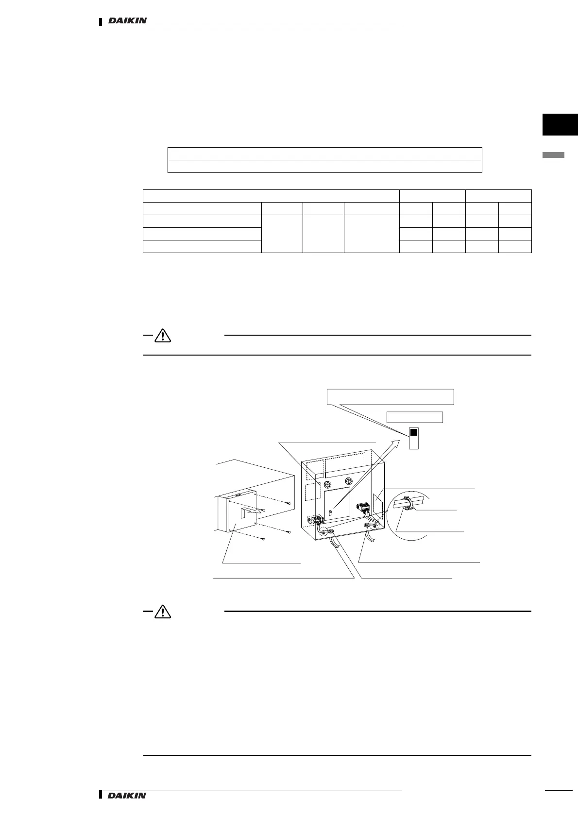
9.9.1 Opening and Shutting the Electric Parts Box and Connecting the Wiring
CAUTION
Be sure to power off before opening the electric parts box.
• Remove the electric parts box lid and wire as shown in the figure below.
CAUTION
• See “Electrical Wiring Diagram label” on the backside of the lid of the electric parts box for electric wiring
work.
• Be sure to attach the sealing material or putty (locally procured) to hole of wiring to prevent the infiltration
of water as well as any insects and other small creatures from outside. Otherwise a short-circuit may
occur inside the electric parts box.
• When clamping the wires, be sure no pressure is applied to the wire connections by using the included
clamping material to make appropriate clamps. Also, when wiring, make sure the lid on the electric parts
box fits snugly by arranging the wires neatly and attaching the electric parts box lid firmly.
When attaching the electric parts box lid, make sure no wires get caught in the edges. Pass wiring
through the wiring through holes to prevent damage to them.
• Make sure the remote controller wiring, the wiring between the units, and other electrical wiring do not
pass through the same locations outside of the unit, separating them by at least 50mm, otherwise
electrical noise (external static) could cause mistaken operation or breakage.
Length of outdoor-indoor transmission wiring … max 1000m (total wiring length 2000m)
Length of remote controller wiring between indoor unit and remote controller … max 500m
Units Power supply Fan motor
Model Hz Volts Voltage range MCA MFA kW FLA
VKM50GAMV1, VKM50GAV1
50 220-240V
Max. 264V
Min. 198V
4.3 15 0.28×2 1.9×2
VKM80GAMV1, VKM80GAV1 4.3 15 0.28×2 1.9×2
VKM100GAMV1, VKM100GAV1 4.3 15 0.28×2 1.9×2
SS1
X1M
X3M
A3P
A1P
A2P
NOR.
M
H
Electric parts box lid
Space for installation of
adapter PC board (KRP2A1)
Space for installation of
adapter PC board
(KRP50-2)
Factroy setting
Power supply wiring and Ground wiring Power wiring through-hole
Transmission wiring through-hole
Do not change the switch settings.
NOTE) A3P: VKM-GAMV1 series only
SS1 is the switch for setting the remote controller.
The unit will not run if the settings are changed.
Clamp
(accessory)
Resin Clamp parts
 Loading...