Do you have a question about the Daikin VRV RXYMQ-A Series and is the answer not in the manual?
Essential safety instructions for repair and maintenance personnel.
Explanation of symbols used in the manual for quick information.
Records of changes and updates made to the manual.
Details on the naming conventions for outdoor and indoor units.
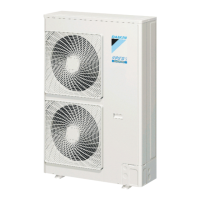
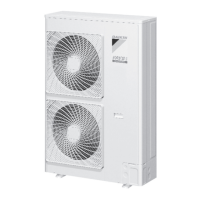
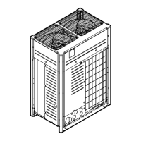
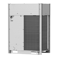
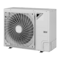
Visual identification of outdoor and VRV indoor unit models.
Information on connection ratios and outdoor unit combinations.
Technical specifications for the RXYMQ-A series heat pump.
Schematic diagrams of refrigerant piping for outdoor and indoor units.
Identification of key components within the outdoor unit.
Lists compatible wired and wireless remote controllers for indoor units.
Details on buttons and display elements of BRC1E63, BRC1H81, and BRC4M series.
Procedure for setting remote controllers as Main or Sub.
Steps for setting addresses for wireless remote controllers and receivers.
Configuration of group addresses for centralized control systems.
Accessing service and maintenance settings via remote controller.
Overview of system operation logic and control sequences.
Procedures for abnormal shutdown and system stop.
Management of compressor and crankcase heater during standby.
Processes for controlling compressor and fan during startup.
Details on compressor, fan, and valve control during normal operation.
Mechanisms for preventing system damage due to abnormal conditions.
Specific operational controls like oil return and defrost.
Control logic for indoor units including temperature and airflow.
Configuration options for indoor units via remote controller or app.
Setup parameters for outdoor units including DIP switches and modes.
Procedures for initial checks, checkpoints, and test runs.
Pre-service checks, precautions, and refrigerant properties.
Troubleshooting guide based on observed system symptoms.
Displays and corrective actions for error codes shown on remote controller.
Lists error codes displayed on the outdoor unit's segment display.
Detailed error codes, descriptions, and troubleshooting steps.
Procedures for checking various system components and parameters.
Electrical wiring diagrams for outdoor and VRV indoor units.
| Series | RXYMQ-A |
|---|---|
| Type | Heat Pump |
| Refrigerant | R410A |
| Operating Temperature Range (Cooling) | -5°C to 46°C |
| Maximum Piping Length | 1000m |
| Cooling Capacity | Varies by model |
| Heating Capacity | Varies by model |
| Energy Efficiency Ratio (Cooling) | Varies by model |
| Coefficient of Performance (Heating) | Varies by model |
| Sound Pressure Level (Outdoor Unit) | Varies by model |
| Power Supply | 380-415V, 50Hz, 3-Phase |
| Maximum Height Difference | 50 m |