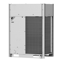
Do you have a question about the Daikin VRV RXYMQ5AYFK and is the answer not in the manual?
Crucial warnings and cautions for safe operation and maintenance.
Illustrates refrigerant flow and component connections for the outdoor unit.
Illustrates refrigerant flow and component connections for VRV indoor units.
Prevents activation of devices due to high pressure increase.
Protects compressors against transient decrease of low pressure.
Protects compressor internal temperature against discharge pipe issues.
Prevents tripping due to inverter abnormalities or overcurrent.
Prevents compressor damage from abnormal heating or operation.
Guides configuring indoor unit settings via remote controller.
Sets specific application requirements for the outdoor unit.
Details DIP switch settings for PCB replacement.
Explains settings made using BS buttons on the PCB.
Verifies prerequisites before performing a test operation.
Lists critical items to check before and during test operation.
Step-by-step guide for conducting test operations.
Procedure for powering on the unit and initiating checks.
General approach to identifying and resolving issues.
Essential safety and handling precautions for maintenance.
Explains error/warning display and corrective actions for BRC1E63.
Explains error display and actions for BRC1H81 Series.
Lists all error codes and their descriptions.
Provides sub-codes for detailed error diagnosis.
Troubleshooting for error code E5.
Troubleshooting for error codes C4, C5, C9.
Troubleshooting for error code C1-01.
Troubleshooting for error code A8.
Troubleshooting for error code U0 (Cooling).
| Model | RXYMQ5AYFK |
|---|---|
| Category | Heat Pump |
| Refrigerant | R410A |
| Power Supply | 50Hz |
| Operating Temperature (Cooling) | -5 to 46°C |
| Operating Temperature (Heating) | -15 to 24 °C |

