Troubleshooting by Indication on the Remote Controller
152
Note:
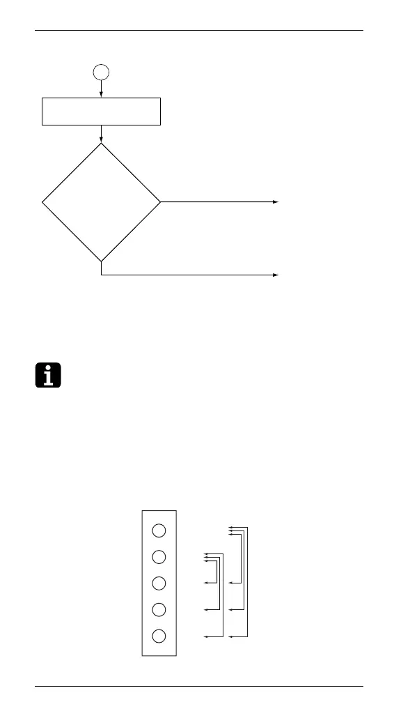
∗1. Check procedure for fan motor connector
(1) Power OFF the fan motor.
(2) Remove the connector on the PCB to measure the
following resistance value.
Judgement criteria: resistance value between each
phase is within ±20%
Connector for signal wires.
Replace the
inverter PCB.
zFor fan motor
1: replace the
inverter PCB
zFor fan motor
2: replace the
fan inverter
PCB
A
YES
Check if the
resistance of the
fan motor lead wire
between Vcc and UVW
and between GND
and UVW are
balanced.
NO
Replace the fan
motor.
Check the connector of
the fan motor (∗1).
GND
Measure the
resistance
between Vcc-
UVW and
GND-UVW.
Vcc
W
V
U
3 Orange
2 Blue
1 Yellow
5 Gray
4 Pink
X2A