www.DaikinApplied.com 67 IOM 1322 • WATER-COOLED SCROLL COMPRESSOR
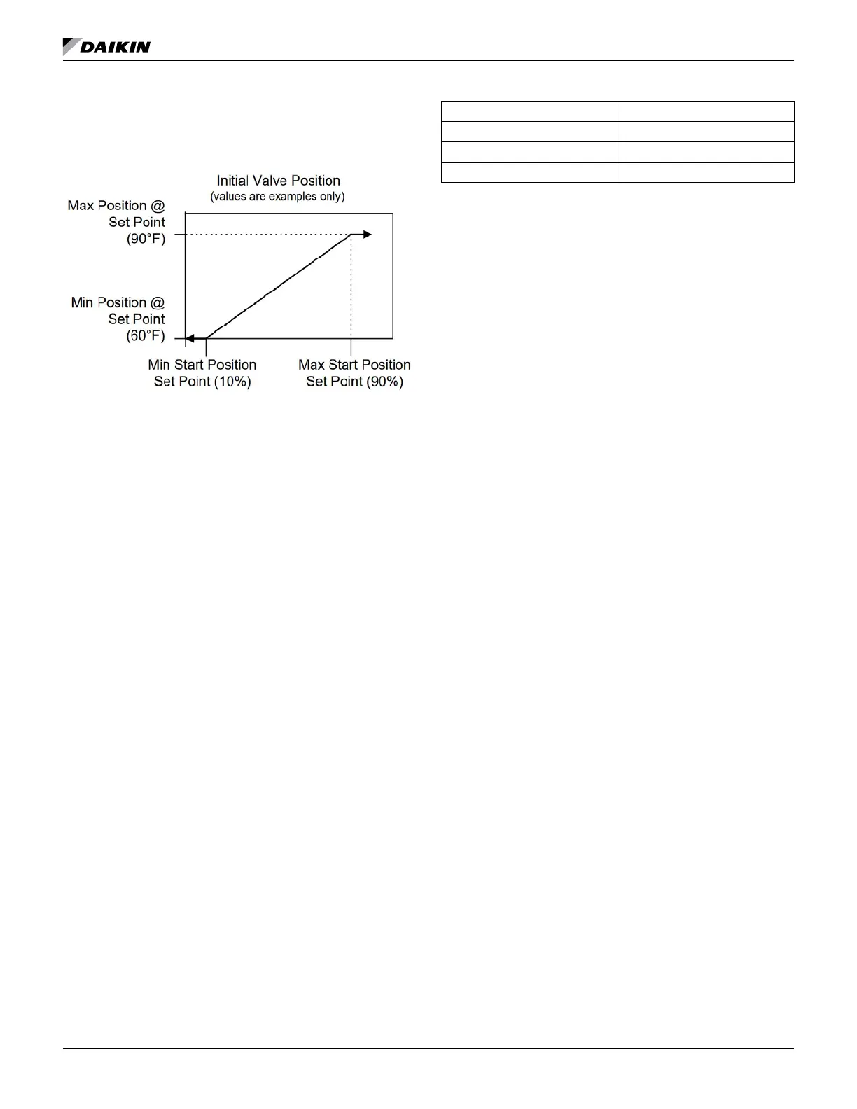
When the condenser pump is not in the RUN state, the valve
output will be set as a function of entering condenser water
temperature (ECWT)) per the following graph.
Operation After Start
When the condenser pump is in the RUN state, the valve
output will be controlled in one of two modes as specied by
the Valve/VFD Control set point. The controlled parameter
will be the condenser entering water temperature. When the
desired output signal varies from 0 to 100%, the output voltage
will vary as shown below.
0 to 10 VDC (Valve Type = NC to tower)
10 to 0 VDC (Valve Type = NO to tower)
This mode is operational when the Valve/VFD Control set point
is set to Valve Set Point OR Valve SP/VFD Stage. In this mode
the valve output is varied with a proportional-derivative (PD)
algorithm (with dead band) in order to maintain the controlled
parameter (CP) at the desired value. The output is always
limited between the Valve Control Range (Min) set point and
the Valve Control Range (Max) set point. A valve increment
shall be computed once every 5 seconds according to the
following equation.
Increment = [(Error) * (Error Gain set point)] + [(Slope) * (Slope
Gain set point)]
Where: Error = ECWT – Valve Set Point Slope = (Present
CP) – (Previous CP)
When the Error is > the Valve Deadband set point, the valve
position analog output (% of full scale) is updated according to
the following equation.
New %Position = Old %Position + Increment/10.
This mode is only operational when the Valve/VFD Control
set point is set to Valve Stage. In this mode the valve output
is controlled as for Valve Set Point mode (above) except that
the active set point for the controlled parameter is selected
according to the following table.
Active Set Point
0 Valve Set Point
1 Stage #1 ON
2 Stage #2 ON
When the Valve/VFD Control set point is set to None,
Valve Setpoint, OR Valve Stage, this output will be set to 0.
Otherwise, it will be controlled in a manner identical to Valve
Stage Mode (above) except that (1) it will be kept at zero until
the rst fan stage is ON and (2) the following set points do not
apply.
Valve Control Range (Min)
Valve Control Range (Max)
Valve Type
Compressor Start/Stop Timing
This section determines when to start or stop a compressor.
There are two separate functions used, one for staging up and
one for staging down.
Stage Up Now
The Stage Up Now ag is set based on the following tests:
If Unit mode = Cool AND
no compressors are running AND
LWT error > Start delta + 0.5 * Control Band AND
Motor Protect Timer expired AND
Stage up timer expired THEN
Stage Up Now = True
If Unit Mode = Cool AND
At least one compressor is running AND
LWT error > 0.5 * Control band AND
Pulldown rate <= Max pulldown rate AND
Compressors running < unit capacity limit AND
Stage up timer expired THEN
Stage Up Now = True
If Unit mode = Heat AND
no compressors are running AND
LWT error > Start delta + 0.5 * Control Band AND
Motor Protect Timer expired AND
Stage up timer expired THEN
Stage Up Now = True
If Unit Mode = Heat AND
At least one compressor is running AND
LWT error > 0.5 * Control band AND
Pulldown rate <= Max pulldown rate AND
Compressors running < unit capacity limit AND
Stage up timer expired THEN
Stage Up Now = True