Do you have a question about the Daikin Navigator WWV and is the answer not in the manual?
Details hazards and their potential consequences, using DANGER, WARNING, CAUTION, and NOTICE classifications.
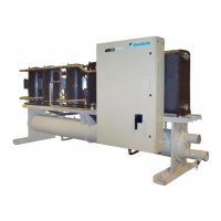
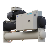
Describes Templifier units and their capabilities, including heating and cooling modes.
Explains the model designation system for WWV chillers, breaking down each part.
Lists temperature and other operating limits for the WWV chillers.
Provides guidance on selecting the proper location for chiller installation, including clearance requirements.
Details the steps for inspecting the unit upon arrival and before installation.
Explains how to engage with and use the unit's lifting brackets safely.
Discusses the importance of proper lifting equipment selection and use.
Outlines precautions for storing the chiller for extended periods, especially in humid environments.
Lists and describes the components for heat exchanger water piping, including valves and sensors.
Discusses the importance of adequate system water volume for chiller operation and stability.
Explains the factory configuration of drain plugs and their installation before filling.
Explains how variable speed pumping affects flow and efficiency.
Provides guidelines on using glycol solutions in the chiller system.
Explains the purpose and function of pressure relief valves for safety.
Warns against operating the system with the three-way valve in the Mid Position.
Details the Type A knockdown method, where components are bolted together for field disassembly.
Provides dimensional and weight data for different compressor models.
Lists dimensions and weights for various combined unit configurations.
Lists dimensions and weights for separated evaporator and condenser units.
Illustrates the power wiring connections within the VFD.
Shows the locations for vessel blockoffs during disassembly.
Details the steps for reassembling the Type B knockdown unit.
Lists the operating limits for Templifier units, including pressure and temperature.
Provides guidelines for source water piping installation for Templifier models.
Provides warnings regarding groove couplings and flow switch installation.
Discusses the use of glycol solutions in Templifier systems and their implications.
Details the wiring for the unit's control circuit, including pump interlocks.
Provides guidelines for connecting the chiller to on-site generators.
Illustrates the single-point power source connections for the unit.
Explains the function of the oil return solenoid valve.
Identifies the location of various components on the front view of the unit.
Lists and identifies components visible from the top view.
Lists and identifies components visible from the back view.
Provides an overview of the chiller's control system components and their interconnections.
Outlines the duties and responsibilities of the unit operator.
Lists analog input signals for the CC1 module.
Lists analog input signals for the Evaporator EXV1 module.
Details settable parameters at the unit level, including defaults and ranges.
Describes the setting for compressor type, which affects available modes and parameters.
Lists set points related to tower fan staging, including on/off temperatures and delays.
Details unit-specific alarms and operational limits.
Covers settings for administration, logging, and saving/restoring configuration.
Explains evaporator LWT error and EWT slope calculations.
Details manual and automatic control of the compressor's Variable Volume Ratio (VR).
Explains how the unit mode is determined by set points and inputs.
Describes the three possible control states of the unit: Off, Auto, and Shutdown.
Details the three control states for evaporator pumps: Off, Start, and Run.
Explains the conditions for transitions between unit states like Auto, Shutdown, and Off.
Outlines the logic for selecting the primary and backup evaporator pumps.
Details the three control states for condenser pumps: Off, Start, and Run.
Explains the conditions for enabling and disabling the first and second fan stages.
Describes how the bypass valve position is controlled based on configuration settings.
Explains how the cooling tower fan VFD speed is controlled.
Details the logic for controlling unit capacity in Cool Mode, including staging.
Explains the limits placed on unit capacity in Cool Mode.
Describes the RapidRestore option for faster restarts after power loss.
Explains how approach values are calculated for evaporators and condensers.
Illustrates the different states a circuit can be in and how they transition.
Details how the compressor is controlled via VFD and digital outputs.
Explains the minimum time between compressor starts and stops.
Describes the function of the three solenoid valves for compressor volume ratio.
Explains how the Evaporator EXV controls refrigerant flow to the evaporator.
Details how alarms are logged, stored, and displayed in the system.
Explains the snapshot log which stores parameter values before an alarm occurs.
Describes how to export alarm, snapshot, and event logs to an SD card.
Outlines the methods by which alarms are signaled to the operator.
Details the trigger, action, and reset conditions for evaporator flow loss alarms.
Details the trigger, action, and reset conditions for condenser flow loss alarms.
Explains the function and reset procedure for the emergency stop switch.
Describes the ground fault protection feature and its alarm conditions.
Details the triggers and conditions for low evaporator pressure alarms.
Details the triggers and conditions for high condenser pressure alarms.
Describes the triggers for high discharge temperature alarms.
Details the conditions that trigger a high oil pressure difference alarm.
Lists various fault conditions reported by the compressor VFD.
Describes the alarm condition for over voltage in the compressor VFD.
Details the conditions for a condenser pressure sensor fault alarm.
Details the conditions for an evaporator pressure sensor fault alarm.
Describes the event where the compressor unloads due to low evaporator pressure.
Describes the event where high condenser pressure causes a hold condition.
Describes the event where high VFD temperature causes unloading.
Details the event that triggers a shutdown due to low pressure ratio.
Explains how to navigate and change parameter values on the controller.
Describes the types of lines and navigation within the controller's menus.
Details the operator level password and its access capabilities.
Outlines essential checks and procedures before the initial startup of the unit.
Provides instructions for installing and calibrating the flow switch.
Details the steps for setting up the flow switch, including the teach function.
Offers guidelines for mounting the flow switch remotely from the unit.
Explains the display indications after completing the flow switch teach adjustment.
Describes the display for the upper range of minimum flow adjustment.
Explains the meaning of the flow switch's LED indicators for flow status.
Describes the indication when the flow is above the display range.
Details the steps for performing a temporary shutdown of the unit.
Outlines the steps to restart the unit after a temporary shutdown.
Discusses the type of oil used for compressor lubrication and handling precautions.
Explains the procedure for removing and renewing the oil filter.
Details the steps for reassembling the oil filter housing with a new element.
Advises on periodically checking and tightening electrical terminals.
Lists inspection areas for the compressor VFD, including general, wiring, terminals, and relays.
Provides a schedule for weekly, monthly, and annual maintenance tasks.
Outlines the terms and conditions of the product's limited warranty.
Lists essential electrical checks to be performed before startup.
Details various miscellaneous checks required before unit startup.
