EasyManua.ls Logo

Daikin AGZ030E User Manual

Daikin AGZ030E
112 pages
To Next Page IconTo Next Page
Page #1 background imageLoading...
Page #1 background image
Installation, Operation,
and Maintenance Manual
Trailblazer
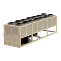
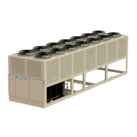
Air-Cooled Scroll Chillers
Model AGZ, E Vintage
30 to 240 Tons (100 to 840 kW)
HFC-410A Refrigerant
50/60 Hz
IOM 1206-7
Group: Chiller
Part Number: IOM1206-7
Date: July 2016

Questions and Answers:

Daikin AGZ030E Specifications

General IconGeneral
BrandDaikin
ModelAGZ030E
CategoryChiller
LanguageEnglish

Summary

Installation and Application Information

Installation and Application Information (Continued)

Operating and Standby Limits

Details the maximum and minimum ambient and fluid temperatures for unit operation and standby.

Chilled Water Piping

Covers requirements for field-installed water piping, including strainers and flow switches.

Water Flow Limitations

Explains constant and variable evaporator flow limitations and their impact.

High Ambient Operation

Addresses requirements for unit operation in high ambient temperatures.

Condenser Coil Options and Coating Considerations

Describes condenser coil materials, coatings, and their suitability for environments.

Evaporator Freeze Protection

Details methods and components for protecting the evaporator from freeze-up.

Refrigerant Schematics

Refrigerant Schematics (Continued)

Electrical Data (Continued)

Typical Field Wiring Diagram (Single-Point Connection)

Illustrates the typical field wiring diagram for single-point power connections.

Typical Field Wiring Diagram (Multi-Point Connection)

Depicts the typical field wiring diagram for multi-point power connections.

Single Point Electrical Data Tables

Provides electrical data for single-point connections, including ratings and lug ranges.

Single Point Electrical Data Tables (Continued)

Lists single-point electrical data for models 120E through 240E.

Multiple Point Electrical Data Tables

Provides electrical data for multiple-point connections for models 030E through 110E.

Multiple Point Electrical Data Tables (Continued)

Lists multiple-point electrical data for models 120E through 240E.

Unit Controller Operation

Unit Controller Operation (Continued)

Controller Inputs and Outputs

Lists and describes analog and digital inputs and outputs for controllers and modules.

Set Points

Explains that unit-level set points are adjustable and details their default values and ranges.

Set Points (Continued)

Details set points for scheduling, sensor offsets, and BAS inputs.

Dynamic Set Point Ranges

Provides dynamic set point ranges for cooling LWT, freeze protection, and ambient lockout.

Circuit Level Set Points

Describes set points applicable to individual refrigerant circuits for mode, compressor, and fan control.

Sequence of Operation

Cool Mode

Details the sequence of operations for the chiller in Cool Mode from start to shutdown.

Sequence of Operation (Continued)

Cool Mode (Continued)

Further details the Cool Mode sequence, including managing unit capacity and circuit shutdowns.

Ice Mode

Outlines the sequence of operations for the chiller when running in Ice Mode.

Ice Mode (Continued)

Further details the Ice Mode sequence, managing capacity and initiating shutdown.

Circuit Sequence of Operation

Explains the operational sequence for individual refrigerant circuits.

Unit Functions

Unit Functions (Continued)

Freeze Protection

Explains conditions for activating evaporator pump for freeze protection.

Unit Capacity Control

Details how unit capacity is controlled, including compressor staging and delays.

Circuit Functions

Circuit Control Logic

Explains conditions for circuit enabling and compressor availability.

Circuit Functions (Continued)

Compressor Control

Details how compressors should run only in run or pumpdown states.

EXV Control and Superheat Target

Explains EXV control states and how the suction superheat target is selected.

Alarms

Alarms (Continued)

Circuit Fault Alarms

Lists circuit fault alarms, including pressure and sensor faults.

Using the Controller

Using the Controller (Continued)

Optional Low Ambient Fan VFD

Optional Low Ambient Fan VFD Overview

Explains the function of the VFD fan control for low ambient operation.

Optional Low Ambient Fan VFD (Continued)

Startup and Shutdown Procedures

Pre Startup

Covers pre-startup checks for mechanical, piping, and electrical systems.

Startup

Provides steps for starting the chiller, including controller familiarization and setpoint configuration.

Startup and Shutdown Procedures (Continued)

Unit Maintenance

Unit Maintenance (Continued)

Planned Maintenance Schedule

Provides a schedule for weekly, monthly, and annual maintenance tasks.

Refrigerant Charging

Details the procedure for recharging the unit with R-410A refrigerant.

Troubleshooting Chart

Compressor Will Not Run

Lists possible causes and corrective steps for a compressor that will not run.

Compressor Noisy Or Vibrating

Provides possible causes and corrective actions for a noisy or vibrating compressor.

High Discharge Pressure

Lists potential causes and corrective steps for high discharge pressure issues.

Low Suction Pressure

Details possible causes and corrective steps for low suction pressure problems.

Troubleshooting Chart (Continued)

Compressor Will Not Stage Up

Lists possible causes and corrective steps for compressors failing to stage up.

Compressor Oil Level Issues

Provides possible causes and corrective steps for incorrect compressor oil levels.

Motor Overload Relays or Circuit Breakers Open

Lists possible causes and corrective steps for motor overload relays or circuit breakers opening.

Compressor Thermal Protection Switch Open

Details possible causes and corrective actions for the compressor thermal protection switch opening.

Warranty Registration Form (Scroll)

Warranty Registration Form (Scroll) (Continued)

Limited Product Warranty

Related product manuals