TURN SIGNAL LAMPS
When the left (lighting) control stalk of the multi-
function switch is activated (Fig. 1), the turn signal
system illuminates the selected right or left turn sig-
nal indicator and the turn signal lamps begin to
flash. The turn signal lamps include a bulb integral
to each front lamp unit and each tail lamp unit, as
well as a repeater lamp bulb located on each front
fender above the front wheels. When the turn signal
system is activated, the turn signal switch circuitry
within the multi-function switch and the electronic
circuitry of the wipers, turn signals and engine start
control module within the fuse block will repeatedly
energize and de-energize the turn signal relay
located in the fuse block. The turn signal relay
switches battery current from a fused ignition switch
output fuse in the fuse block to the appropriate turn
signal indicator and turn signal lamps.
The ElectroMechanical Instrument Cluster (EMIC)
contactless relay will generate repetitive, audible
turn signal “click” sounds to emulate the sounds of a
conventional electro-mechanical turn signal flasher
at one of two rates to coincide with the flashing of
the turn signals. The slow rate emulates normal turn
signal operation, while the fast rate emulates “bulb
out” turn signal operation.
SPECIFICATIONS - LAMPS / LIGHTING - EXTE-
RIOR
BULB SPECIFICATIONS
LAMP BULB
Backup P21W - 12V 21W
Brake & Rear Park P21/5W - 12V 21/5W
Center High Mounted
Stop
P21W - 12V 21W
Clearance W3W - 12V 3W
Front Fog H1 - 12V 55W
Front Position W5W - 12V 5W
Front Turn, Park & Side
Marker
3457 NA - 12V 28/7.5W
Amber Glass
Low Beam Headlamp H7 - 12V 55W
High Beam Headlamp H1 - 12V 55W
License Plate C5W - 12V 5W
Rear Side Marker R5W - 12V 5W
Rear Turn P21W - 12V 21W
Side Repeater W5W - 12V 3W
BACKUP LAMP BULB
REMOVAL
(1) Disconnect and isolate the battery negative
cable.
(2) If the vehicle is so equipped, remove the trim
from the inside of the right or left rear corner pillar.
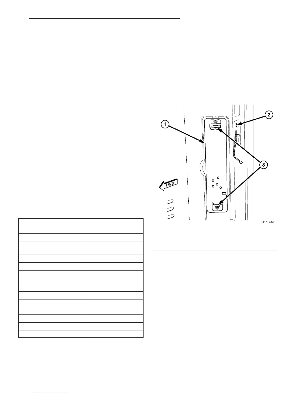
(3) From inside the vehicle, use hand pressure to
push the two latch tabs toward the center of the tail
lamp unit socket plate and pull the socket plate
straight out from the inner rear pillar (Fig. 2).
(4) Pull the socket plate away from the inner rear
pillar far enough to access the backup lamp bulb
(Fig. 3).
Fig. 2 Tail Lamp Socket Plate Remove/Install
1 - SOCKET PLATE
2 - INNER REAR PILLAR
3 - LATCH TAB (2)
VA LAMPS/LIGHTING - EXTERIOR 8L - 5