EasyManua.ls Logo

Dakota Digital VHX-69C-CAM User Manual

Dakota Digital VHX-69C-CAM
40 pages
To Next Page IconTo Next Page
Page #1 background imageLoading...
Page #1 background image
Manual # 650318
VHX-69C-CAM
Dakota Digital VHX Instrument Installation
For ‘69 Chevy Camaro systems
Your new VHX-69C-CAM kit will include:
Installation
1. You may be able to access all of the fasteners with the dash carrier installed, removing the entire
assembly may not be necessary. First, remove the clear lenses from the front. Next, remove the
original gauge internals; they are held into the housing with nuts from the backside. The
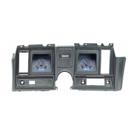
discarded pieces should match the photo below:
Control Box
Foam Tape
10
-
32x1” Mounting Screws w/
nylon washers
10-32x1.5” Mounting Screws
w/ nylon shoulder washers
Two CAT5 Cables
(To connect Displays to
Control Box)
Universal Sensor
Pack
VHX Displays
(shown with protective film)

Questions and Answers:

Dakota Digital VHX-69C-CAM Specifications

General IconGeneral
Display TypeLCD
CompatibilityUniversal
Oil Pressure Range0-100 PSI
Temperature Range100-300°F
Product LineVHX Series
Input Voltage12 V
Communication ProtocolCAN
FeaturesProgrammable, Backlit
Voltage Range8-18V

Summary

Installation Overview

Kit Components List

Lists all components included in the VHX-69C-CAM kit.

Initial Dash Preparation

Steps for preparing the dash by removing lenses and internal gauges.

VHX System Features

Digital Display Capabilities

Details on LCD display functions, mileage, and performance readings.

Integrated Indicators and Outputs

Describes built-in indicators like turn signals and special outputs.

Installation Guidelines

Care and Cleaning

Instructions for cleaning the VHX system components.

Control Box Mounting

Guidance on selecting and securing the control box location.

Wiring and Connections

Control Box Terminal Functions

Detailed explanation of each terminal on the VHX control box.

Power, Grounding, and Signals

Instructions for connecting power, ground, signals, and sensors.

System Setup and Calibration

Speedometer Calibration

Procedures for calibrating the speedometer using Auto Cal or Adjust modes.

Tachometer and Gauge Configuration

Settings for tachometer, engine, and individual gauge parameters.

Display and Lighting Adjustments

Customizing backlight brightness, message display, and LCD contrast.

Information and Odometer Presets

Accessing system information and setting the initial odometer reading.

Troubleshooting Guide

Power and System Issues

Solutions for systems not powering on or status LED malfunctions.

Gauge and Display Errors

Diagnosing and resolving problems with incorrect or missing gauge readings.

Technical Specifications

Electrical and I/O Data

Details on voltage ranges, signal levels, and output current.

Service and Warranty

Repair and Support Procedures

Procedures for obtaining service, repair, or technical assistance.

Warranty Terms and Conditions

Explanation of the limited lifetime warranty coverage and exclusions.

Related product manuals