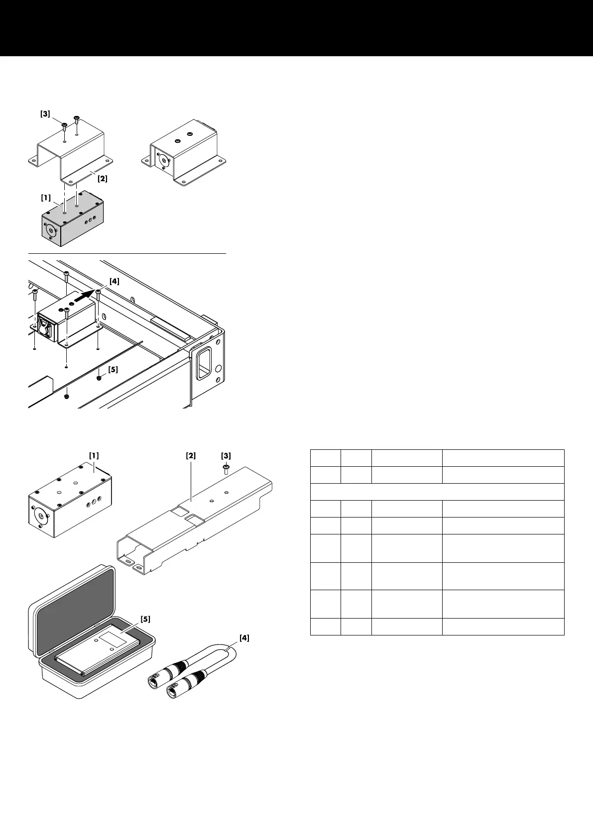
Assembly
1. First attach the ArraySight sender unit [1] to the flying frame
adapter [2].
2. Fix the sender unit with the two panhead screws (M4 x 12)
[3].
3. As the sender unit assembly is mounted from the bottom of the
J flying frame, turn frame by 180°.
4. Position the frame onto an appropriate and flat surface.
5. Attach the sender unit assembly to the mounting plate of the
frame with the laser unit facing towards the front of the frame.
6. Fix the sender unit assembly using the four panhead screws
(M5 x 18) [4] and the self securing nuts (M5) [5].
7. Recheck your work and ensure all screws are properly
tightened.
9.1.2 Z5710.002 Mounting instructions
Scope of supply
Pos.
Qty. d&b Code Description
1 Z5710.002 d&b ArraySight set V-Series
Including:
[1] 2 Z5711 ArraySight sender unit
[2] 2 V Flying frame adapter
[3] 12 Panhead screw (Torx T20)
M4 x 12
[4] 2 K6006.200.00 Shielded CAT5e 1:1 cable,
30 m (100 ft)
[5] 1 Z5712 ArraySight meter unit
within transport case
1 D2735.EN .01 ArraySight Manual
d&b ArraySight Manual 1.7 en26
 Loading...