35
Fahrzeug-/Funktionsdecoder ab Firmware-Version 1.11
35
Locomotive/Vehicle function decoder from firmware version 3.12
PD21A
Specifications PD21A
Dimensions [mm]
Total load
Maximum motor current
Maximum operating voltage
Function outputs for light: LV, LR (dimmable)
Function outputs: AUX1, AUX2 (dimmable)
21,2 x 15,5 x 2,9
1,0 A
1,0 A
30 V
each 150 mA
each 300 mA
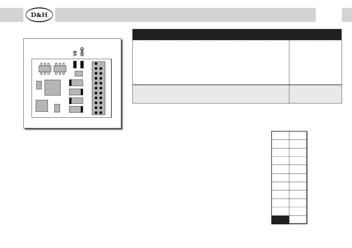
Connecting option
21 pin socket board for direct plugging (mTc21)
PD21A-4
21 pin interface
1 22
2 21
3 20
4 19
5 18
6 17
7 16
8 15
9 14
10 13
11 12
–
--
--
–
–
–
LR
LV
--
--
Index
G1
G2
GND
M1
M2
--
VS
AUX1
AUX2
–
–
M1, M2 ..............Motor connection 1, 2
G1, G2 ............... Track connection 1, 2
LV, LR ................Front light, rear light (each 150 mA)
AUX1, AUX2 .....Additional function 1, 2 (each 300 mA)
VS ......................Supply voltage
GND ..................Ground (0 V)
If necessary: Connect blue wire (common return conductor) to VS.
You can connect a buffer capacitor to VS (+) and GND (-).
 Loading...