2 DKRCI.PI.SC0.D2.02 / 520H5637 © Danfoss A/S (AC-SMC/MWA), 01-2012
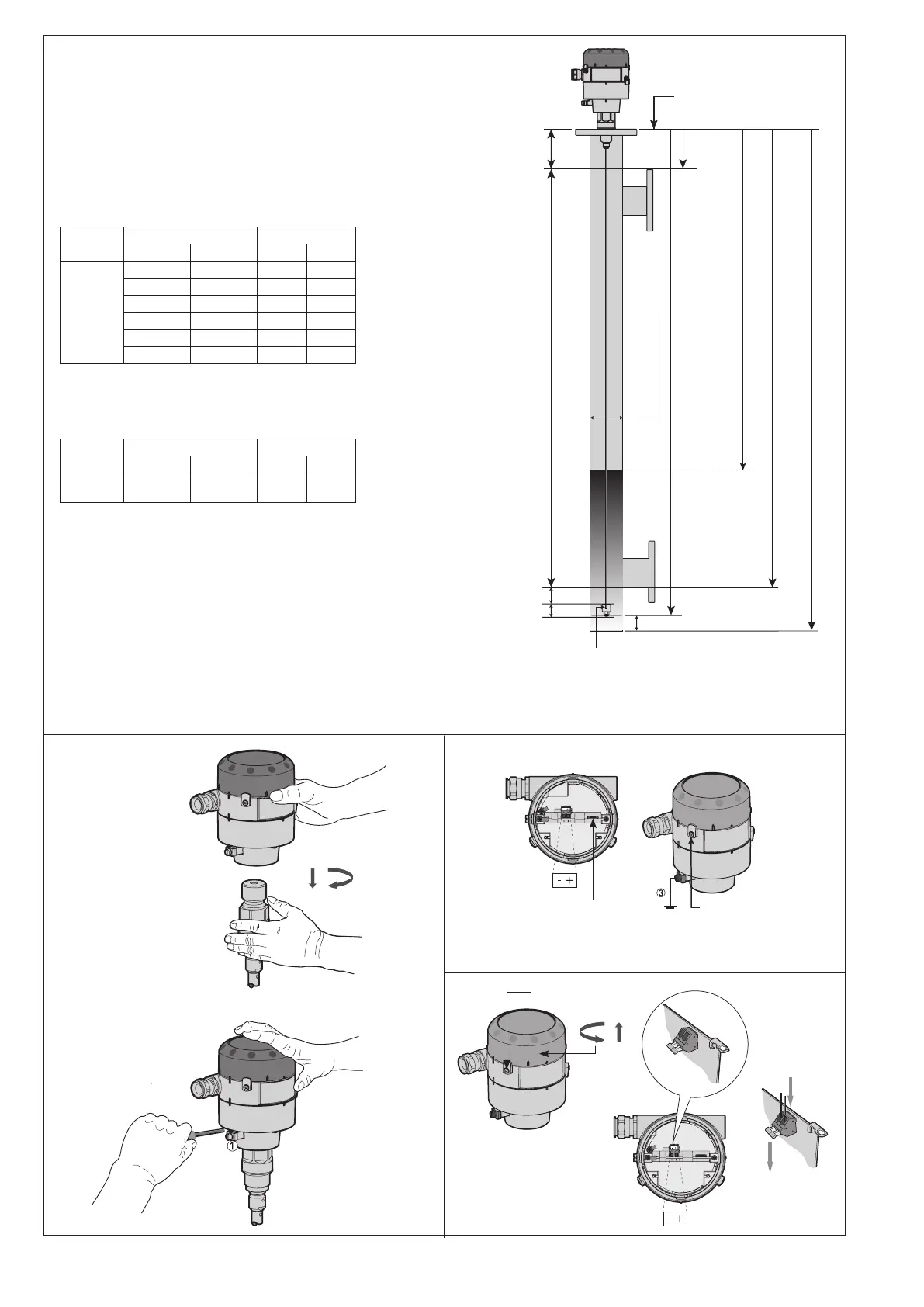
Fig. 5
Top dead zones
120 mm (4.7 in.)
Measuring range
Bottom dead zone (see tables)
Counterweight: 33 mm (1.3 in.)
Min: 20 mm (0.8 in.)
Steel wire
insertion length:
12 mm (0.5 in.)
Probe length*
4 mA (0 %)*
Inner length of the standpipe
Danfoss
M84H0017_1
20 mA
(100 %)*
Standpipe
diameter: 2-4 in.
Reference point
Distance
Surface level
Bottom deadzone values based on the
factory setting of dielectric constant
Refrigerant Probe length range Bottom dead zone
[mm] [in.] [mm] [in.]
Ammonia,
HFC, HCFC
800 31.5 115 4.2
801 - 999 31.5 - 39 120 4.7
1000 - 1999 39 - 79 150 5.9
2000 - 2999 79 - 118 180 7.1
3000 - 3999 118 - 157 210 8.3
4000 - 5000 157 - 197 240 9.4
Improved Bottom dead zone values
after the adjustment of dielectric constant
Refrigerant Probe length range Bottom dead zone
[mm] [in.] [mm] [in.]
Ammonia,
HFC, HCFC
800 - 5000 31.5 - 197 90 3.5
Fig. 7
Fig. 8
Danfoss
Danfoss
M84H0010_1
Cover stop
2.5 mm/0.2 in.
Allen Key
Connector
for HMI
Loosen cover stop
Danfoss
M84H0031_1
Fig. 6
* Values to be entered into HMI Quick Setup menu
and recorded on the setting label.
Stick the setting label onto the Signal Converter either
inside or outside.
 Loading...


