4 DKRCI.PI.SC0.E5.02 / 520H5658 © Danfoss A/S (AC-MCI/MWA), 11-2013
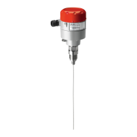
AKS 4100/4100U
connected to PLC
Fig. 12
+
–
AKS 4100/4100U
+
–
Active
Analog Input 4-20 mA
14-30 V d.c.
M84H0029_1
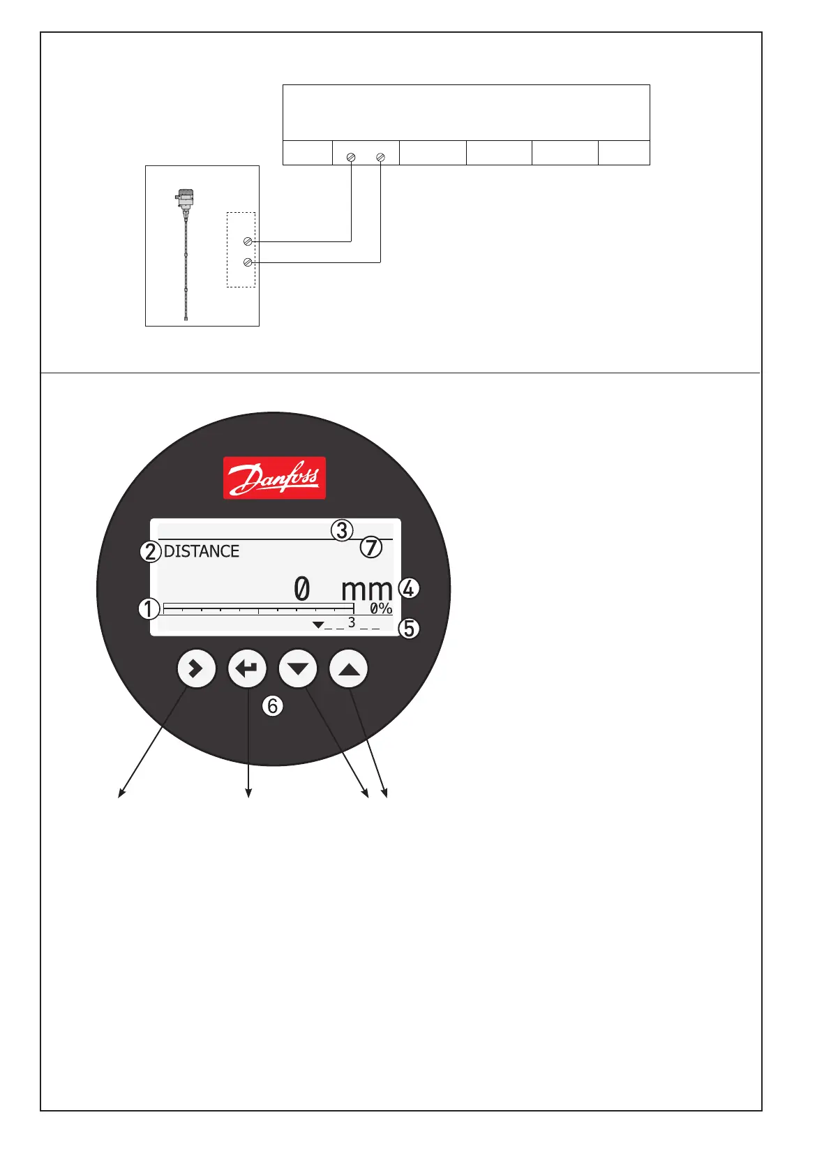
Enter menu system
Enter QUICK SETUP
Unit change at
distance/level
readout:
m, cm, mm, in, ft
Change between:
Distance*
Level**
Output (%)***
Output (mA)****
4-20 mA output displayed as bar graph
and in percentage [%]
Measurement name (in this example,
DISTANCE)
Device tag name
Measurement reading and unit
Device status (markers)
Marker 1, 2 and 3 (Error)
Hardware problem; the Signal Converter
hardware is defective. Contact Danfoss.
Marker 4 and 5 (Notification)
Depending on the level, the marker is ON or
OFF. Used for Danfoss service information
only.
Keypad buttons
Flashing star indicating unit in operation.
* DISTANCE is a display option.
If the display is set to “DISTANCE” the displayed
value will be the distance from the Reference
point to the top surface of the liquid refrige-
rant (see fig. 6).
** LEVEL is display option.
If the display is set to “LEVEL” then the value
displayed will be:
PROBE LENGTH (entered in QUICK SETUP)
– DISTANCE (see fig. 6)
*** OUTPUT (%) is display option.
Will represent the level of refrigerant,in
percent, scaled (entered in QUICK SETUP)
according to: SCALE 4 mA (0%), SCALE
20 mA (100%) (see fig. 6).
**** OUTPUT I (mA) is display option.
Will represent the level of refrigerant,
in 4-20 milliampere, scaled (entered in
QUICK SETUP) according to: SCALE 4 mA
(4 mA), SCALE 20 mA (20 mA) (see fig. 6).
*
AKS 4100
Fig. 13