This document provides instructions for the Danfoss ON/OFF Zone valve, specifically models AMZ 112 and AMZ 113. It covers installation, manual control, and wiring diagrams for various control devices.
Function Description
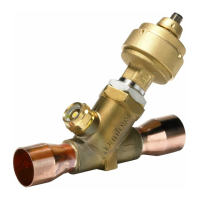
The Danfoss AMZ 112 and AMZ 113 are ON/OFF zone valves designed for controlling the flow of heating or cooling water in hydronic systems. These valves operate by either fully opening or fully closing, providing two-position control. The "ON/OFF" designation indicates that they do not offer modulating control but rather a simple binary state.
The core function of these valves is to direct or block the flow of fluid based on a control signal, typically from a thermostat or a building management system. When the valve is "ON" (open), fluid flows through it; when it is "OFF" (closed), fluid flow is stopped. This makes them suitable for zone control in residential and commercial buildings, allowing individual areas or circuits to be heated or cooled independently.
The document illustrates two main types of manual control:
- AMZ 112 Manual Control: This model features a 90° rotation mechanism for manual operation. The valve can be manually set to "OPEN" or "CLOSE" by rotating a lever or knob through a 90-degree arc. This manual override is useful during installation, maintenance, or in case of power failure, allowing the system to be operated without electrical input. The visual representation shows a lever that can be moved between two stops, indicating the open and closed positions.
- AMZ 113 Manual Control: This model utilizes a 180° rotation mechanism for manual operation. Similar to the AMZ 112, it allows for manual opening or closing of the valve. The 180-degree rotation might offer a more distinct visual or tactile indication of the valve's position. The diagram shows a rotating element that can be turned through 180 degrees to switch between "OPEN" and "CLOSE" states.
Both models also support automatic operation, where an electrical signal from a control device drives the valve actuator. The "AUTO" section in the manual control diagrams shows the valve in its automated configuration, ready to respond to electrical commands.
Important Technical Specifications
While specific numerical values for flow rates, pressure ratings, or power consumption are not explicitly stated in the provided diagrams, the document implies several key technical aspects through its wiring and installation instructions:
- Electrical Supply: All control devices and the zone valves themselves operate on a 230V electrical supply, as indicated in the wiring diagrams for thermostats and switches. This is a common voltage for HVAC systems in many regions.
- Fuse Rating: The wiring diagrams consistently specify a F1A/250V fuse. This indicates that the control circuit for the zone valve should be protected by a 1 Ampere fuse rated for 250 Volts. This fuse protects the control components from overcurrents.
- Switch Types:
- AMZ 112/113 SPST Switch: This refers to a Single-Pole, Single-Throw switch. In this configuration, the valve's operation is controlled by a simple ON/OFF signal. The diagram shows a Black (L) line connected to terminal 1 (OPEN PORT A), a Blue (N) neutral line connected to terminal 2, a Brown (L) line connected to terminal 3 (CLOSE PORT B), and a Red (L) line connected to terminal 4, which provides an "Out signal OPEN (AMZ112)" or "A+B (AMZ113)". This suggests that the AMZ 112 uses a single signal for opening, while the AMZ 113 might use a combined signal for its A+B ports.
- AMZ 112/113 SPDT Switch: This refers to a Single-Pole, Double-Throw switch. This type of switch provides two distinct output states, allowing for more direct control over the open and closed positions. The wiring is similar to the SPST, but the internal switch logic offers two separate contact positions, typically for "OPEN" and "CLOSE" commands.
- Port Designations: The diagrams for the AMZ 113 manual control and AUTO sections show "PORT B" and "PORT A" with corresponding "A" and "B" terminals and an "AB" common terminal. This suggests that the AMZ 113 might be a three-port valve (one inlet, two outlets, or vice versa) or a two-port valve with specific wiring for different control scenarios, possibly indicating a changeover function or a bypass. The "AB" terminal likely represents a common connection.
- Control Devices: The document details compatibility with various control devices:
- Room thermostat RET 230: A basic room thermostat for ON/OFF control.
- Programmable Room Thermostat TP 5000: Offers programmable scheduling for heating/cooling.
- Programmable Room Thermostat TP 7000 / TP 7000M: More advanced programmable thermostats, potentially with additional features (M might indicate a specific model variant or feature set).
- Thermostat KP-RT with a switch contact: A thermostat with an integrated switch for direct control.
- Switch contact: A simple switch for direct ON/OFF control.
Usage Features
The Danfoss AMZ 112 and AMZ 113 zone valves are designed for ease of integration into hydronic systems and offer several usage features:
- Versatile Control Options: The valves can be controlled by a wide range of thermostats and switches, from simple ON/OFF room thermostats (RET 230, KP-RT) to advanced programmable thermostats (TP 5000, TP 7000/M). This flexibility allows them to be used in various applications, from basic single-zone control to more complex multi-zone systems with time-based scheduling.
- Manual Override: Both AMZ 112 (90° rotation) and AMZ 113 (180° rotation) models include a manual control feature. This is a crucial safety and convenience feature, allowing users or technicians to manually open or close the valve without electrical power. This is particularly useful during system commissioning, troubleshooting, or in the event of a power outage, ensuring that the system can still be operated or isolated.
- Clear Installation Instructions: The "Installation AMZ 112" and "Installation AMZ 113" sections provide visual guidance on how the valves should be physically installed in a pipe system. The "FORBIDDEN" symbol clearly indicates incorrect installation practices, emphasizing the importance of proper orientation and connection to ensure reliable operation and prevent damage. This visual instruction helps prevent common installation errors.
- Wiring Diagrams: Comprehensive wiring diagrams are provided for connecting the valves to various control devices. These diagrams clearly label terminals (L, N, 1, 2, 3, 4, A, B, C, AB), wire colors (Black, Blue, Brown, Red), and fuse requirements (F1A/250V). This detailed information simplifies the electrical installation process, ensuring correct and safe wiring.
- SPST and SPDT Switch Compatibility: The valves are compatible with both SPST (Single-Pole, Single-Throw) and SPDT (Single-Pole, Double-Throw) switch configurations. This broad compatibility allows for different control strategies. SPST is suitable for simple ON/OFF control, while SPDT can offer more precise control over the open and closed states, potentially allowing for feedback or more complex logic in the control system.
- Zone Control Capability: The primary usage feature is their ability to enable zone control. By installing these valves in different heating/cooling circuits, individual zones within a building can be controlled independently, leading to improved comfort and energy efficiency by only conditioning occupied or desired areas.
Maintenance Features
While the document does not explicitly detail a "maintenance schedule" or "troubleshooting guide," several aspects can be inferred regarding maintenance:
- Manual Override for Service: The manual control feature is not only for emergency operation but also serves as a critical maintenance feature. It allows technicians to isolate a zone or keep it open/closed during system flushing, repairs, or component replacement without needing to power down the entire system or rely on electrical signals. This simplifies maintenance procedures and enhances safety.
- Robust Design (Implied): The visual representation of the valves suggests a robust construction suitable for continuous operation in hydronic systems. While specific materials are not mentioned, the design appears to be industrial-grade, implying durability and reduced need for frequent component replacement.
- Fuse Protection: The specified F1A/250V fuse in the control circuit is a key maintenance-related feature. It protects the valve's actuator and control electronics from electrical faults. If the valve stops responding, checking and replacing this fuse would be a primary troubleshooting step, indicating a simple and accessible point of maintenance.
- Clear Wiring for Troubleshooting: The detailed wiring diagrams are invaluable for troubleshooting. If a valve is not operating correctly, a technician can easily trace the electrical connections, verify voltage at different terminals, and check for continuity based on the provided schematics. This significantly reduces diagnostic time.
- Component-Level Replacement (Implied): While not explicitly stated, the modular nature of zone valves often allows for the replacement of the actuator head independently of the valve body. This can simplify maintenance by allowing a faulty electrical component to be swapped out without draining the entire system, saving time and resources. The "M" symbol in the manual control section might indicate a motor or actuator component that could be a replaceable part.
- Visual Position Indication: The 90° and 180° rotation indicators for manual control provide a clear visual indication of the valve's current state (open or closed). This is helpful during maintenance to quickly ascertain the valve's position without needing to rely on electrical feedback or system pressure readings.
In summary, the Danfoss AMZ 112 and AMZ 113 zone valves are fundamental components for hydronic zone control, offering reliable ON/OFF operation, flexible integration with various control systems, and practical features for both installation and maintenance.