EasyManua.ls Logo

Danfoss TE 5 - User Manual

Danfoss TE 5
2 pages
Print Icon
To Next Page IconTo Next Page
Loading...
© Danfoss | DCS (az) | 2018.02
067R9608
067R9608
1
2
3
1
2
3
Installation guide
Thermostatic expansion valves
Type TE 5, TE 12, TE 20 and TE 55
DKRCC.PI.A00.C6.02 | 1
Max. test pressure P
test
:
32 bar / 465 psig
Min. 5% Ag
TE12 tight torque =
45 ± 5 Nm / 33 ±3.7 ft-lbsAllen key M6
Type
Torque ± 5%
Nm kpm ft-lbs
TE 5 10 1.1 7.4
TE 12 13 1.4 9.6
TE 20 13 1.4 9.6
TE 55 15 1.6 11.1
Max. working pressure PS / MWP:
28 bar / 400 psig
Refrigerants:
R407F, R407A, R448A, R449A, R452A, R513A,
R404A, R507, R22, R134a and R407C.
For complete list of approved
refrigerants, go to www.danfoss.com
Solder
Flange
Torx T25
Max. 4Nm
(3ft-lbs)
Question and Answer IconNeed help?

Do you have a question about the Danfoss TE 5 and is the answer not in the manual?

Summary

Thermostatic Expansion Valves TE Series

Refrigerant Compatibility and Pressure Ratings

Lists approved refrigerants and specifies maximum working and test pressures for TE valves.

Solder Connection Installation Guide

Step-by-step instructions and considerations for installing valves via soldered connections.

Flange Connection Installation Guide

Details the procedure and requirements for installing valves using flange connections.

Tightening Torques and Required Tools

Specifies torque values for connections and lists necessary tools like Allen and Torx keys.

TE Valve Superheat and Capacity Performance

Superheat Adjustment and Static Settings

Guidance on calculating and setting superheat, including static superheat values by range.

Valve Capacity Ratings by Refrigerant

Presents tables of rated capacities for TE 5, TE 12, TE 20, and TE 55 valves across various refrigerants.

Overview

This document provides an installation guide for Danfoss thermostatic expansion valves, specifically the TE 5, TE 12, TE 20, and TE 55 types. These valves are designed to regulate the flow of refrigerant into evaporators, ensuring optimal performance in refrigeration systems.

Function Description

Thermostatic expansion valves (TXVs) are crucial components in refrigeration and air conditioning systems. Their primary function is to control the superheat of the refrigerant at the evaporator outlet. Superheat is the difference between the actual temperature of the refrigerant vapor and its saturation temperature at the same pressure. By maintaining a constant superheat, the TXV ensures that the evaporator is fully utilized without allowing liquid refrigerant to return to the compressor, which could cause damage.

The TE series valves operate based on the principle of balancing forces. A temperature-sensing bulb, filled with a charge similar to the system's refrigerant, is attached to the evaporator outlet. Changes in the superheat at the evaporator outlet cause the pressure within the bulb to change, which in turn acts on a diaphragm inside the valve. This diaphragm movement adjusts the opening of the valve's orifice, thereby regulating the flow of liquid refrigerant into the evaporator. If the superheat increases, indicating insufficient refrigerant in the evaporator, the bulb pressure rises, opening the valve further to allow more refrigerant in. Conversely, if the superheat decreases, the bulb pressure drops, closing the valve to reduce refrigerant flow.

The valves are designed to work with a wide range of refrigerants, including R407F, R407A, R448A, R449A, R452A, R513A, R404A, R507, R22, R134a, and R407C. A complete list of approved refrigerants is available on the Danfoss website. This versatility makes them suitable for various applications in commercial refrigeration, air conditioning, and heat pump systems.

Usage Features

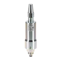
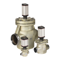
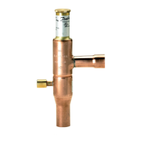
The TE series valves are available in different configurations to suit various system requirements. The document illustrates three main types: TE 5, TE 12/TE 20, and TE 55, each with distinct physical dimensions and connection types.

Installation: The installation process involves several key steps, whether using solder or flange connections.

  • Solder Connections: For solder connections, it is crucial to ensure a minimum of 5% silver content in the solder. The installation guide shows a diagram of the soldering process, emphasizing the need for proper technique to prevent damage to the valve. This typically involves applying heat evenly and quickly to avoid overheating the valve body, which could affect its internal components.
  • Flange Connections: For flange connections, specific torque values are provided to ensure a secure and leak-free seal. For the TE12, the tight torque is specified as 45 ± 5 Nm (33 ± 3.7 ft-lbs). This precision is vital to prevent refrigerant leaks and maintain system integrity.
  • Orifice Installation: The document details the installation of the orifice, which is a critical component that determines the valve's capacity. The orifice is inserted into the valve body, and a specific torque (Max. 4 Nm or 3 ft-lbs) is required for the Torx T25 screw that secures it. This ensures the orifice is correctly seated and does not restrict flow or cause leaks.
  • Allen Key M6: An Allen key M6 is used for certain adjustments or connections, indicating the use of hexagonal sockets for secure fastening.
  • Capillary Tube and Bulb Installation: The capillary tube connects the sensing bulb to the valve body. The sensing bulb must be properly attached to the evaporator outlet pipe to accurately measure superheat. The document shows different OD (Outer Diameter) sizes for the capillary tube connections: 1/2-5/8 in. (12-16mm), 3/4-7/8 in. (18-22mm), and 1-13/8 in. (25-35mm). This variety ensures compatibility with different pipe sizes.

Pressure Ratings: The valves are designed to withstand significant pressures:

  • Max. working pressure (PS / MWP): 28 bar / 400 psig
  • Max. test pressure (Ptest): 32 bar / 465 psig These ratings indicate the robustness of the valves and their suitability for high-pressure refrigeration systems.

Superheat Adjustment: The valves feature a superheat adjustment mechanism, which allows fine-tuning of the superheat setting to optimize system performance. The document illustrates how to adjust the superheat using an Allen key. Turning the adjustment screw clockwise typically increases superheat, while turning it counter-clockwise decreases it. The static superheat is set at 4 K / 7.2°F, but for range B, it needs to be adjusted. The document provides guidelines for superheat adjustment based on the valve type and range:

  • TE 5, TE 12 (N, NL, NM ranges): ~0.5 K / 1°F superheat
  • TE 5, TE 12 (B range): ~1.5 K / 3°F superheat
  • TE 20, TE 55 (NL, NM ranges): ~0.5 K / 1°F superheat
  • TE 20, TE 55 (B range): ~1 K / 2°F superheat These adjustments are critical for achieving optimal evaporator performance and preventing compressor damage.

MOP (Maximum Operating Pressure) Functionality: Some models may include an MOP function, which limits the evaporator pressure to a maximum value. This protects the compressor from overload, especially during start-up or rapid changes in load. The diagram shows a "12 MOP" indicator, suggesting that certain TE 12 models incorporate this feature.

Rated Capacity: The document includes a comprehensive table of rated capacities for different refrigerants (R407F, R407A, R448A/R449A, R404A/R507, R22, R134a, R407C) and orifice sizes (0.5 to 13). These capacities are provided in both kW and TR (tons of refrigeration) and are based on specific operating conditions:

  • Evaporating temperature (te): 4.4°C / 40°F
  • Condensing temperature (tc): 38°C / 100°F
  • Refrigerant temperature ahead of valve (t1): 37°C / 9°F This information is essential for selecting the correct valve and orifice for a given refrigeration system.

Maintenance Features

While the document primarily focuses on installation and usage, several aspects imply ease of maintenance:

  • Replaceable Orifices: The presence of a table listing various orifice sizes and the illustration of orifice installation suggest that orifices are replaceable. This allows for easy capacity adjustment or replacement of a worn-out orifice without needing to replace the entire valve body. This modular design simplifies maintenance and extends the lifespan of the valve.
  • Cross-Reference Table: The cross-reference table, which includes "Old code no." and "Part of old TE 12 valve assembly. Need to change to TE 5 valve body and element for replacement," indicates that Danfoss provides clear guidance for replacing older components with newer, compatible parts. This ensures that maintenance and upgrades can be performed efficiently, even on older systems.
  • Clear Torque Specifications: Providing precise torque values for screws (e.g., Torx T25 for orifice, flange connections) is a maintenance feature. It ensures that components are tightened correctly, preventing damage from overtightening or leaks from undertightening. This precision contributes to the longevity and reliability of the valve.
  • Allen Key Adjustments: The use of standard tools like an Allen key for superheat adjustments makes field maintenance straightforward and accessible.
  • Robust Construction: The high working and test pressure ratings suggest a robust construction designed for durability, which inherently reduces the frequency of maintenance.

In summary, the Danfoss TE series thermostatic expansion valves are designed for precise refrigerant flow control, offering versatility with multiple refrigerants and robust construction. Their installation is guided by clear instructions for both solder and flange connections, with specific torque values for critical components. The ability to adjust superheat and replace orifices contributes to their adaptability and ease of maintenance, making them a reliable choice for various refrigeration applications.

Danfoss TE 5 Specifications

General IconGeneral
Supply Voltage24 V AC/DC
RefrigerantR134a, R404A, R407C, R410A, R507, R22
Control SignalPWM
ApplicationRefrigeration
Relative Humidity95% RH
Storage Temperature Range-40°C to +85°C

Related product manuals