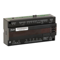
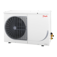
The Danfoss OPTYMA™ Control three-phase is a sophisticated controller designed for comprehensive management of three-phase refrigeration systems, particularly for cold room applications. It is suitable for systems up to 7.5 HP, whether static or ventilated, and supports both off-cycle and electrical defrosting methods. The device integrates an innovative design with front access to key protective components, making it an ideal choice for efficient and reliable refrigeration control.
Function Description
The primary function of the OPTYMA™ Control is to provide complete management of three-phase refrigeration systems. This includes precise control of the cold room temperature, accurate to 0.1 °C, and the ability to display evaporator temperature based on configurable parameters. The controller supports both direct and pump-down control of the motor compressor unit, with the selection made via terminal block connections in preset models.
A key feature is its robust alarm signaling system, which alerts users to various issues such as probe errors, minimum and maximum temperature alarms, and compressor protection trips. In some preset models, it also includes a "man-in-cold-room" alarm for enhanced safety.
The device manages evaporator fan operation and offers both automatic and manual defrost control, accommodating static and heating element defrosting types. For convenience and energy efficiency, it includes room light activation, which can be triggered via a panel key or a door switch. An auxiliary relay provides configurable activation options, allowing for flexible integration with other system components.
Security is addressed through parameter access with a password function, offering four different selectable restriction levels to prevent unauthorized changes. The unit also incorporates a general magnetothermic circuit breaker, accessible from the front panel, which cuts the general power supply for safety. Additionally, an adjustable motor circuit breaker for compressor protection is accessible from the front panel in preset models, ensuring the longevity and safe operation of the compressor.
Usage Features
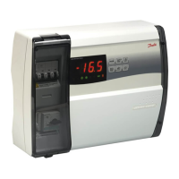
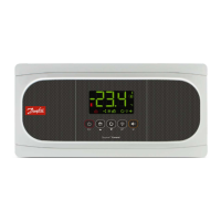
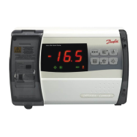
The OPTYMA™ Control is designed for ease of use, featuring LED icons that clearly signal the plant status. Its electronic control system is equipped with a wide LED display and user-friendly buttons, simplifying operation and monitoring.
Users can easily display and adjust the cold room temperature setpoints. The control panel includes dedicated keys for various functions: an "AUX" key for auxiliary relay control (configurable by parameter), an "UP/MUTE WARNING BUZZER" key to increase values and silence alarms, a "STAND BY" key to activate or deactivate the system (indicated by a flashing LED when in stand-by), a "Room temperature SETTING / SET" key for displaying and modifying setpoints, a "DOWN / MANUAL DEFROST" key to decrease values and initiate manual defrost, and a "ROOM LIGHT" key for controlling the cold room light.
The programming interface is structured into two levels to enhance safety and simplify operation. Level 1 (User Level) allows configuration of frequently modified SETPOINT parameters, such as differential, defrost interval, end-of-defrost setpoint, max defrost duration, drip duration, fan pause after defrost, and minimum/maximum temperature alarms. Level 2 (Installer Level) provides access to general parameter programming for various controller operating modes, including door switch status, fan status, sensor presence, defrost type, compressor protection contact status, compressor safety time for door switch, fan shutdown temperature, and fan differential. Access to Level 2 requires specific key combinations and cannot be directly accessed from Level 1, ensuring that critical system settings are protected.
The device also supports a pump-down function for compressor control, which is electromechanically managed within the panel. A password function activates after two minutes of inactivity, displaying "000" and requiring a numerical input for access, with a universal number available in case the password is forgotten.
Maintenance Features
Maintenance of the OPTYMA™ Control is designed to be straightforward but must be performed by skilled and authorized technicians to ensure safety and correct functioning. Before any repair or maintenance work on the electrical system, it is crucial to disconnect the voltage by placing the general power supply switch in the open position (O) and verifying the absence of voltage with a detector. Any defective elements should be replaced with original spare parts only.
For external corrections, the control power supply must be safely switched off, either by turning the main switch to the OFF position and securing the transparent polycarbonate front cover with a padlock, or by cutting off the power supply upstream of the line and securing it with a padlock. Displaying signs indicating maintenance in progress is also recommended.
Specific safety instructions for maintenance operations include ensuring the control is voltage-free, preventing unauthorized personnel access, displaying "Device isolated for maintenance" notices, wearing suitable work clothing (overalls, gloves, shoes, headgear), removing any items that could become entangled, using suitable and correctly cleaned/greased tools, and having all necessary technical documentation (wiring instructions, tables, drawings). Upon completion, all residual materials must be removed, and the inside of the control cleaned carefully. It is imperative that no additional parts are placed inside the control.
Regular maintenance includes checking current absorption on loads after powering up and after a few hours of operation, and ensuring that screws on terminal blocks (including power supply line connection) are sufficiently tight. The motor circuit breaker for the compressor, if present, must be calibrated correctly based on measured absorption, not exceeding the compressor manufacturer's recommendations, to prevent breakdowns or incorrect interventions.
The manual provides step-by-step instructions for installing the unit, including lifting the transparent cover, removing screw covers, undoing fixing screws, opening the housing, bending hinges, and disconnecting the electronic card connector. It also details how to prepare the back panel for wall fixing and the electrical wiring process, emphasizing the use of appropriate cable glands and plugs to maintain the protection rating and proper wire routing to avoid interference.
For alarm/AUX relay switching, specific instructions are provided for opening the front panel, accessing the electronic card, undoing CPU board cover fixing screws, removing jumpers from JP2, and inserting jumpers in JP2 for relay selection according to desired functions. Wiring for the alarm/Aux relay should be routed alongside existing connection cables from the electronic card and housing back panel.
The device also includes a troubleshooting section to address common anomalies not indicated by alarm codes, covering issues like no power supply, general magnetothermic circuit breaker intervention, auxiliary circuits magnetothermic circuit breaker intervention, circuit protection fuse intervention, control in stand-by mode, and pressure switch/Kriwan malfunctions. This comprehensive guide ensures that the OPTYMA™ Control can be effectively installed, operated, and maintained for optimal performance and safety.