
J
Jennifer MillerAug 15, 2025
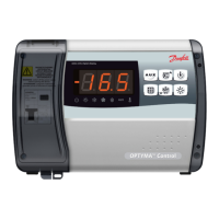
Why Danfoss OPTYMA Control Controller compressor doesn’t start and the display is OFF?
- MmillerjeffreyAug 15, 2025
If the Danfoss Controller compressor doesn’t start and the display is off, check for a power supply issue by ensuring the display on the panel and the plant in operation green light are on. Inspect the ambient probe connections, and replace the sensor if the problem continues. Also, examine the general and auxiliary circuits for tripped breakers; before resetting them, check for short circuits and any absorption anomalies. Finally, verify the secondary circuit protection fuse on the transformer; replace it with a Glass fuse 10x20 F250mA 250V if necessary, ensuring the transformer's secondary absorption doesn't exceed 0.25A and that no extra devices are connected to the Kriwan power supply terminals, and confirm there are no short circuits on the secondary circuit.