Do you have a question about the Danfoss ERC 112D and is the answer not in the manual?
Details on power supply, inputs, outputs, probes, and connectors.
Information on programming, assembly, display, keypad, and operating conditions.
Physical measurements and regulatory certifications for the controller.
Illustrates the electrical connections for ERC 112D and ERC 112C models.
Details on configuring the controller's output relays for various functions.
Explains the ERC front panel layout and button actions for navigation and control.
Instructions on how to change the temperature setpoint using the controller buttons.
Guide on initiating or stopping the manual defrost cycle.
Steps for changing parameters and enabling/disabling ECO mode.
Details on assigning functions to the controller's inputs.
Information on setting up and accessing password protection for different user levels.
Instructions on how to acknowledge and clear active alarms.
The Danfoss ERC 112 Bottle Cooler Controller is a sophisticated device designed for precise temperature management in bottle coolers. It offers a comprehensive suite of functionalities for both basic operation and advanced configuration, ensuring optimal performance and energy efficiency.
The core function of the ERC 112 is to regulate the temperature within a bottle cooler. It achieves this through a control sensor, which continuously monitors the temperature and dictates the compressor's cut-in and cut-out cycles based on a user-defined setpoint. This sensor is typically positioned to measure the return air to the evaporator, providing an accurate representation of the cabinet's internal temperature.
In addition to the control sensor, the ERC 112 can integrate an evaporator sensor, primarily for de-icing purposes. This sensor is strategically placed where ice is expected to melt last, ensuring efficient defrost cycles without impacting the overall cooling performance. The controller also supports a condenser temperature sensor, a crucial safety feature that protects the compressor from high-pressure damage in scenarios like a blocked condenser or a failed condenser fan. This sensor is typically located on the liquid side of the condenser, with proper thermal contact ensured through a metal bracket or tape.
The device features multiple configurable outputs, including relays for the compressor, defrost heater, fan, light, and alarm. These outputs can be assigned various functions, allowing for flexible control over different components of the bottle cooler system. For instance, the compressor relay can be configured for basic ON/OFF operation, while other relays can manage defrost cycles, fan operation, lighting, or trigger alarms.
The ERC 112 also incorporates several input options. Beyond the temperature sensors, it can connect to a door sensor, a light sensor (Danfoss ECO light), and a motion sensor. These inputs enable advanced functionalities such as automatic light control based on ambient light conditions or door status, and potentially energy-saving modes triggered by the absence of motion.
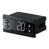
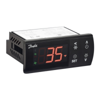
The ERC 112 is designed for user-friendly interaction through its front panel, which includes a 3-digit LED display and four integrated buttons. The display shows the current temperature and various icons indicating the device's status, such as defrost mode or ECO mode. The buttons allow users to navigate the menu, adjust parameters, and activate specific functions.
Changing the setpoint is a straightforward process. Users can press a designated button to display the current temperature, then use UP/DOWN buttons to adjust the desired setpoint. After a brief period of inactivity, the display automatically reverts to showing the current temperature.
Manual defrost can be initiated by a brief press of a specific button. During defrost, a defrost symbol is displayed, indicating the active defrost cycle. The symbol disappears once the defrost is complete. The visibility of the "dEF" text during defrost can be configured based on the cabinet manufacturer's settings.
The controller offers an ECO function, which can be activated by a brief press of a button. When in ECO mode, a green ECO symbol is displayed, indicating that the device is operating in an energy-saving mode.
For advanced configuration, the ERC 112 provides a comprehensive menu structure accessible by pressing and holding a specific button for 5 seconds. This menu is organized into parameter groups, allowing users to scroll through various settings. To select a parameter, users press the lower left button (OK), then use UP/DOWN buttons to adjust the value. The new value is confirmed by pressing the OK button again. The menu also allows users to navigate back to previous levels or exit the menu entirely.
The device includes password protection for its configuration settings, offering three levels of access: "shop" for daily use by shop personnel, "ser" for service technicians, and "OEM" for OEM programming. This ensures that critical settings are not inadvertently altered.
In case of an alarm, the alarm code flashes alternately with the temperature and the alarm symbol. Users can acknowledge the alarm by pressing any button, after which the temperature is displayed, and the alarm symbol remains shown.
The ERC 112 is built for durability and reliability. Its front panel has an IP65 rating, providing protection against dust and water ingress, making it suitable for environments where splashes or dust are common. The rear part of the device has an IP31 rating, with the accessibility of connectors limiting the rating to IP00.
The device is designed for easy assembly, offering three types of mounting: front mounting with brackets, and a fully integrated solution that requires an OEM-specific design of the mounting hole. This flexibility simplifies installation and integration into various bottle cooler designs.
The compressor relay is rated for over 175,000 cycles at full load, indicating a long operational lifespan. The device is also compliant with various international safety and quality standards, including UL60730, NSF, CQC, and GOST R 60730, ensuring its safety and performance.
The modular connector system, with optional output screw terminal adapters, facilitates easy connection and disconnection of components, simplifying maintenance and troubleshooting. The input connector type is Rast2 5 Edge connectors, and the output connector type is RAST 5 standard.
Programming can be done using the Danfoss ERC docking station, which is an integrated system, allowing for efficient setup and configuration. This streamlined programming process contributes to easier maintenance and updates.
| Sensor Type | NTC, PTC, Ni1000, Pt100, Pt1000 |
|---|---|
| Dimensions | 75 mm x 33 mm x 85 mm |
| Sensor inputs | 2 |
| Enclosure rating | IP20 |
| Power consumption | 3 VA |
| Output signal | Relay |
| Housing material | Plastic |
| Application | Refrigeration |
| Relay outputs | 2 |
| Ambient temperature range | -10 - 55 °C |
| Relative humidity | 20% to 80% RH, non-condensing |
| Weight | 0.2 kg |
| Power Supply | 230 V AC ± 10%, 50/60 Hz |
| Supply voltage | 230 V AC ± 10%, 50/60 Hz |
| Storage temperature range | -40°C to +70°C |