EasyManua.ls Logo

Danfoss erc 112 User Manual

Danfoss erc 112
32 pages
To Next Page IconTo Next Page
Page #1 background imageLoading...
Page #1 background image
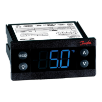
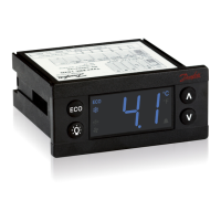
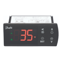
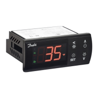
ERC 112 refrigeration controller
Bottle cooler controller
ERC 112
This reference manual is intended to be used primarily by OEMs for the purposes
of programming ERC 112. It may also be useful for technicians. It is not intended
as a user guide for end users.
www.danfoss.com/erc

Other manuals for Danfoss erc 112

Questions and Answers:

Danfoss erc 112 Specifications

General IconGeneral
TypeElectronic Refrigeration Controller
Supply Voltage230 VAC
Relay Outputs3
ApplicationRefrigeration
Digital Inputs1
Protection ClassII
Sensor TypeNTC
Storage Temperature-20°C to 70°C

Summary

Introduction

Application

Temperature control for refrigeration appliances. Front panel mounting.

Advantages

Latest generation CPU, memory, and high-end components for versatile software. Three password levels.

Approvals

List of approvals for end-use applications according to EN/IEC standards.

Password Protected

Three access levels (shop, technicians, OEMs) with password protection.

Typical Applications

Glass Door Merchandiser

No-frost freezer/sub-zero cooler. Details for ERC 112D and ERC 112C models.

Gastro No-frost Freezer

Application for gastro units. Details for ERC 112D and ERC 112C models.

Gastro Cooler

Application for gastro cooler units. Details for ERC 112D and ERC 112C models.

Product Overview

Display and Buttons

Electronic controller with LED display and front panel buttons.

Mounting and Clips

Front mounting procedure and rear mounting clips.

Input/Output Descriptions

Description of inputs (S1-S4, di) and outputs (DO1-DO4).

Quick Programming

Software Tool and Gateway

Programming ERC 112 via PC using software tool and USB gateway.

USB Programming Key

USB key for saving parameter files for mass programming.

Docking Station

High-volume programming tool for assembly lines.

Technical Specifications

Power Supply and Input/Output

Details on power supply, inputs, outputs, probes, and connectors.

Assembly, Display, and Keypad

Information on controller assembly, display type, and keypad.

Operating Conditions and Approvals

Environmental specs, protection, resistance, EMC category, and compliance approvals.

Connections

ERC 112C Wiring

Wiring diagram for ERC 112C (3 relays) showing power, outputs, and inputs.

ERC 112D Wiring

Wiring diagram for ERC 112D (4 relays) showing power, outputs, and inputs.

Code Numbers

Controller Models

Part numbers for GDM-front and CFF-front ERC 112 models.

Sensors and Accessories

Part numbers for temperature sensors, motion sensors, clips, and programming accessories.

Operation

Control Methods

Controller operation via software tool, docking station, or front panel buttons.

Manual Button Operation

Detailed guide for operating the controller using its front panel buttons.

Operation Examples

Examples of common operations like setting temperature, ECO, light, and alarms.

Menu Functions

Thermostat Settings

Parameters for set point, differential, and temperature limits.

Fan Settings

Parameters for fan control, delays, and minimum stop time.

Menu Functions (Continued)

Fan Stop and Light Settings

Fan stop delay on door open, and cabinet light control settings.

Pull Down Settings

Parameters for Super Cool (pull down) function, including initiate temp and duration.

Menu Functions (Continued)

Defrost Settings

Parameters for defrost type, adaptive defrost, and termination temperatures.

Defrost Interval and Duration

Parameters for minimum/maximum defrost intervals and durations.

Menu Functions (Continued)

Defrost Fan and Compressor Control

Parameters for fan during defrost and compressor time consideration.

Defrost Start and Compressor Settings

Defrost start trigger and voltage protection for the compressor.

Menu Functions (Continued)

Error Handling and Compressor Timers

Parameters for sensor error handling, minimum run/stop times, and maximum OFF time.

Door Delay and Condenser Protection

Compressor delay on door open and notes on condenser protection settings.

Menu Functions (Continued)

Condenser Alarm Settings

Parameters for condenser high/low temperature alarms and limits.

Display Settings

Parameters for display intensity, unit, sensor display, and range limit.

Menu Functions (Continued)

Display Delay and Offset

Parameters for display delay filter and temperature offset adjustment.

Defrost Lock and Display States

Lock display during defrost and control display of ECO, Pull down, Holiday, Defrost.

Menu Functions (Continued)

Alarm Settings

Parameters for high/low temperature alarms, delays, and pull down delay.

Door Open Delay and Voltage/Leakage Alarms

Door open delay, voltage alarm, and leakage alarm parameters.

Alarm Buzzer Duration

Parameter for controlling the duration of the audible alarm.

Menu Functions (Continued)

Alarm Auto Clear and Heater Settings

Auto clear alarms and parameters for automatic heater control.

ECO Strategy

Notes on light sensor for ECO strategy and ECO mode ON/OFF.

Menu Functions (Continued)

ECO Mode Actions and Timing

Parameters for ECO actions, delays, shop light, and pull down time.

Shop Close Hour and Holiday Settings

Parameters for shop closing time, early wake-up, and holiday length.

ECO Management

Parameters for ECO and Holiday temperature offsets.

Menu Functions (Continued)

ECO Specific Functions

ECO differential, fan cycles, light control, and light delay.

Assignment Settings

MODBUS safety, air temperature adjustment, and input/output configuration.

Menu Functions (Continued)

Input Configuration (S1-S4)

Configures sensor types and applications for inputs S1-S4.

Digital Input and Output Configuration

Configures digital input (DI) and output relays (D01-D04).

Menu Functions (Continued)

Button Configuration

Assigns functions to short and long presses of controller buttons.

Password Settings

Sets passwords for access levels: Shop, Service, and OEM.

Service Information Settings

Read-only parameters for accumulated run times and controller uptime.

Menu Functions (Continued)

Status and Counter Information

Displays DI status, voltage, DOs status, and various counters.

Version and Identification Information

Shows serial number, SW/HW versions, order numbers, OEM codes, and manufacturing date.

Default Settings and Temperature Display

Resets parameters to OEM defaults and displays sensor temperatures.

Menu Functions (Continued)

Sensor Value Displays

Displays AUX temp, light level, motion state, raw air temp, and ECO switch state.

Display Messages

Describes device status messages like unprogrammed, Eco, defrost, and holiday modes.

Troubleshooting

Common Operational Issues

Troubleshooting for compressor, fan, defrost, and alarm issues.

Display and Alarm Troubleshooting

Diagnosing display problems, weak brightness, and ECO mode issues.

Alarm Trigger Codes and Remedies

Table of alarm codes and their corresponding troubleshooting steps.

Typical Applications (Continued)

Glass Door Merchandiser Applications

Wiring and component details for glass door merchandisers.

Typical Applications (Continued)

Gastro Freezer and Cooler Applications

Wiring and component details for gastro no-frost freezers and coolers.

Application Matrix

ERC 112 Application Mapping

Table mapping applications to ERC types, inputs, and outputs.

Application Matrix Notes

Notes on input selection, connector matching, and sensor options.

Sensor Placement

Control Sensor Placement

Guidelines for placing control sensors in coolers and freezers.

Evaporator Sensor Placement

Guidelines for placing evaporator sensors for de-icing purposes.

Sensor Placement (Continued)

Condenser Sensor Placement

Guidelines for placing condenser sensors to protect the compressor.

Ambient Light and Door Sensor

Placement for ambient light and door sensors, and their function.

Related product manuals