User Guide | Optyma™ control AK-RC 113 three phase
© Danfoss | DCS (vt) | 2020.03 BC317523579312en-000101 | 19
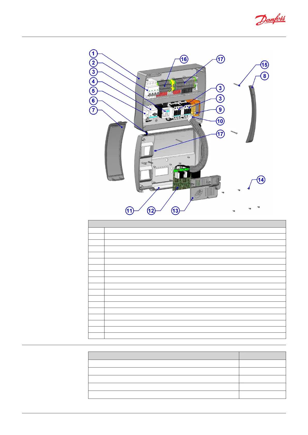
9.2 Part List
Key
Ref. Description
1. Box rear in Abs
2. 4 poles magnetothermic circuit breaker with general switch / general protection function
3. Contactors for units control
4. Compressor protection motor circuit breaker
5. Auxiliary protection 1-pole magnetothermic circuit breaker
6. Box front opening hinges
7. Front cover in transparent polycarbonate
8. Transparent polycarbonate screw cover
9. Auxiliary circuits transformer (N.B. with inside a glass fuse 10 x 20 F250 mA 250 V)
10. Connector for linking panel and the electronic card
11. Front panel
12. Electronic card
13. Electronic card cover
14. Electronic card fixing screws
15. Box closure screws
16. Auxiliary terminal block X1
17. Power terminal block X2
10.0 Ordering
Type Code No.
Optyma Control, three phase (4HP), including 2 sensors, 4.5 – 6.3 A 080Z3221
Optyma Control, three phase (4HP), including 2 sensors, 7 – 10 A 080Z3222
Optyma Control, three phase, (7.5HP), including 2 sensors, 11 – 16 A 080Z3226
Optyma Control, three phase, (7.5HP), including 2 sensors, 14 – 20 A 080Z3227
Sensor EKS 221 (spare part) 084N3210