EasyManua.ls Logo

Danfoss Optyma Plus - User Manual

Danfoss Optyma Plus
18 pages
Print Icon
To Next Page IconTo Next Page
Loading...
Controller for Condensing unit
Optyma Plus
TM
User Guide

Other manuals for Danfoss Optyma Plus

Question and Answer IconNeed help?

Do you have a question about the Danfoss Optyma Plus and is the answer not in the manual?

Summary

Introduction to Optyma Plus Controller

Application Overview

Defines the controller's use for condensing unit control.

Key Advantages and Features

Lists benefits like pressure control, fan speed, and compressor regulation.

Operational Principle

Explains how the controller receives signals and manages cooling demands.

Core Controller Functions

Outlines primary functions such as temperature, fan, and compressor control.

Condensing Temperature Regulation Reference

Details regulation relative to ambient temperature and set points.

Day;Night Operation Mode

Describes the internal clock for switching between day and night settings.

Fan Operation and Speed Control

Internal Fan Speed Regulation

Controls fan speed via terminal 5-6 with relay activation at high speeds.

External Fan Speed Regulation

Uses an external 0-10V signal for fan speed control via terminal 54-55.

Fan Speed at Start-up

Sets initial fan speed ('Jog Speed') for 10 seconds upon restart.

Fan Speed at Low Load Conditions

Maintains a minimum fan speed ('FanMinSpeed') for loads between 10-30%.

Fan Speed Adjustment for Low Temperatures

Lowers fan amplification factor for smoother regulation in cold ambient conditions.

Compressor Operation Management

Compressor Start;Stop and Restrictions

Controls compressor via DI1, with restrictions to prevent frequent cycling.

Discharge Gas Temperature Monitoring

Manages compressor capacity and fan speed based on Td sensor readings.

Economizer Port Liquid Injection

Activates liquid injection to manage discharge temperature near maximum limits.

High Pressure Monitoring and Safety Stop

Monitors condensing pressure and stops compressor if limits are exceeded.

Low Pressure Monitoring and Cut-out

Stops compressor on low suction pressure after minimum ON time.

Pump Down Limit Function

Stops the compressor when suction pressure falls below a defined set value.

Controller Features and Interfaces

Crankcase Heating Element Control

Thermostat function to keep oil separate from refrigerant via a heating element.

Digital Input Functions (DI1, DI2, DI3)

Details the uses of DI1, DI2, and DI3 for various control and safety functions.

Data Communication Capabilities

Built-in MODBUS and optional LON RS485 for data exchange.

External Display Connectivity

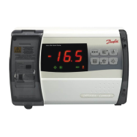
Connects EKA 163B/164B displays for readings and operation.

Override Functionality for System Management

Enables control integration with master gateways or system managers.

Comprehensive Function Survey

Normal Display and Temperature Units

Shows Ts/Tc and allows selection of SI or US units.

Thermostat Set Point and Offset Configuration

Sets the reference temperature and day/night offset.

Refrigeration Start;Stop and Standby Alarm

Manual control options and standby alarm notification.

Night Setback and Reference Ts Settings

Adjusts reference for night operation and suction pressure.

Condensing Temperature Reference Limits

Defines minimum and maximum permitted condensing temperatures.

Discharge Gas Temperature and Alarm Settings

Manages max Td, fan speed, and alarm delays.

Alarm General Behavior and DI2 Alarm Delay

General alarm indication and timing for DI2 input alarms.

Compressor Control Parameters Detailed

Compressor Running Time Parameters

Sets minimum ON-time, OFF-time, and restart intervals for compressor.

Pump Down Limit and Speed Settings

Defines compressor stop pressure and minimum/start speeds.

Compressor Maximum Speed and Night Operation

Sets max speed limits and reduced speed during night operation.

Compressor Control Definition and Td Delay

Configures control modes and delay for high discharge gas temperature.

Pressure Limit Settings (Max Condensing, Min Suction)

Sets maximum condensing and minimum suction pressures.

Pressure Difference and Regulation Tuning

Defines re-start differences and PI regulation parameters.

Liquid Injection Offset and Hysteresis

Configures activation and deactivation points for liquid injection.

Fan Control Parameters

Settings for fan speed regulation, including amplification factor.

Advanced Fan, Clock, and Miscellaneous Settings

Fan Speed Regulation and Adjustment Parameters

Tuning parameters for fan speed changes and amplification.

Fan Speed Start and Low Temperature Jog Settings

Configures initial fan speed and low-temperature jog speed.

Fan Control Mode and Minimum;Maximum Speed

Selects fan control type and sets speed limits.

Manual Fan Speed Control

Allows manual override of fan speed.

Real Time Clock Configuration

Settings for day/night switch times and clock date/time.

Network Address and Access Code Settings

Configures network address and access code for security.

Display, Input, and Sensor Configuration

Display Signal Selection and Pressure Transmitter Ranges

Configures display signal and Ps/Pc transmitter ranges.

Refrigerant Type and Digital Input D2 Functions

Selects refrigerant and defines D2 input functionality.

Condensing Unit Type and S3 Sensor Configuration

Sets unit type and configures S3 for discharge gas temperature.

Save Factory Settings and Taux Sensor Usage

Saves current settings and defines Taux sensor function.

Crankcase Heating Element Timing and Power

Sets timing and power points for the crankcase heating element.

Operating Time Tracking and Alarm Counts

Reads unit, compressor, and heating element operating times and alarm counts.

Alarm Counts and Oil Return Management

LP, Discharge Alarm Counts, and Oil Return Speed Limit

Tracks LP/discharge alarms and sets speed limit for oil return.

Oil Return Management Time and Boost Settings

Configures time limits and boost speed for oil return management.

Service Functions for System Monitoring

Lists service functions for reading various parameters and statuses.

Understanding Operating Status Codes

Normal Operation and Compressor Status Codes

Explains status codes for normal regulation and compressor activity.

Refrigeration Stop and Manual Control Status

Details status codes for refrigeration stopped by switch or manual control.

Refrigerant Selection and Safety Cut-out Status

Covers status codes for missing refrigerant and safety cut-outs.

Other Displayed Operating Status Indicators

Indicates status for password, stopped regulation, and unit type selection.

Fault Messages and Alarm Configuration

Fault Message Codes and Data Communication Descriptions

Lists fault codes and actions for data communication.

Data Communication Alarm Settings and Destinations

Configures alarm importance and destinations for data communication.

Controller Operation and Menu Navigation

Display and LED Indicator Functions

Explains display values and front panel LED indicators.

Button Navigation and Menu Access Procedures

Guides users on how to navigate menus and change settings.

Menu Setting Examples and Set Point Adjustment

Provides step-by-step examples for setting parameters and set points.

Quick Start Procedure for Regulation

Outlines steps for a fast initial setup and regulation start.

Menu Survey Summary

Presents a summary table of functions, parameters, and settings.

Detailed Parameter Settings and Values

Alarm and Compressor Parameter Details

Lists specific min/max values for alarm and compressor parameters.

Control, Fan, and Clock Parameter Details

Details settings for regulation tuning, fan control, and real-time clock.

Miscellaneous Parameter Settings

Provides settings for network address and access codes.

Advanced Parameter Configuration and Service

Display, Input, and Refrigerant Configuration Details

Detailed settings for display, inputs, and refrigerant selection.

Unit Type, Sensor, and Factory Setting Management

Configures unit type, Taux sensor, and saves factory settings.

Heating Element Timing and Operating Time Tracking

Sets crankcase heating timing and tracks operating hours.

Oil Return Management and Alarm Count Details

Configures oil return parameters and reads alarm counts.

Service Functions and Readouts

Lists various service functions for reading system status and parameters.

Connections and Installation Guidelines

Digital Input and Pressure Transmitter Connections

Details wiring for DI inputs and pressure transmitters (Pc, Ps).

Sensor and Display;Communication Connections

Covers sensor wiring and EKA display/RS485 connections.

Analog Outputs, MODBUS, and Supply Voltage

Wiring for AO outputs, MODBUS, and supply voltage.

Relay Outputs and DI3 Connection

Wiring for Alarm, Comp, CCH, Fan, Aux relays, and DI3 input.

Electrical Noise and Installation Considerations

Guidelines for minimizing electrical noise and proper installation practices.

Technical Data and Specifications

Supply Voltage, Sensor, and Measuring Ranges

Electrical supply, sensor types, and measuring ranges.

Accuracy, Display, and Digital Input Specs

Accuracy of measurements, display type, and digital input requirements.

Electrical Connections and Cable Requirements

Details on electrical connections, cable lengths, and relays.

Analog Outputs, Environmental, and Density Specs

Specifications for analog outputs, operating environments, and density.

Mounting, Weight, Data Communication, and Approvals

Mounting options, weight, communication standards, and certifications.

Load Limitations for Relays

Important notes on capacitive loads and motor connections for relays.

Ordering Information and Accessories

Optyma Plus Controller and Plug Accessories

Ordering codes for the controller and plug accessories.

Display and Data Communication Module Accessories

Ordering codes for various display types and LON module.

Wire and Programming Key Accessories

Ordering codes for display wires and programming keys.

Overview

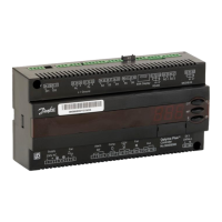
This document serves as a user guide for the Danfoss Optyma Plus™ controller, designed for condensing unit applications. It provides comprehensive information on the controller's functions, operational principles, connections, and troubleshooting.

The Optyma Plus™ controller is engineered to manage condensing unit operations efficiently. Its primary function is to control condensing temperature in relation to the outside ambient temperature, ensuring optimal performance and energy efficiency. The controller receives a signal for cooling demand and initiates compressor operation accordingly. For variable speed compressors, suction pressure (converted to temperature) is regulated to a set temperature value. Condenser pressure regulation is achieved by controlling the fan speed based on ambient temperature and a set reference, maintaining the desired condensing temperature. Additionally, the controller manages a crankcase heating element to prevent oil from mixing with refrigerant and activates liquid injection into the suction line if discharge temperature becomes excessively high.

Usage Features:

The controller offers a range of features to enhance usability and operational flexibility:

  • Fan Operation: The fan speed can be regulated internally or externally. Internal speed regulation uses terminals 5-6, while external regulation for larger fan motors with insufficient internal outlets connects to terminals 54-55, sending a 0-10V signal. The user can select the control method via menu 'F17'. The fan also has specific behaviors at start-up (Jog Speed) and low loads (FanMinSpeed) to ensure smooth operation and prevent frequent start/stops in low ambient temperatures.
  • Compressor Control: Compressor operation is initiated by a signal at DI1. To prevent frequent cycling, the controller incorporates minimum ON time, minimum OFF time, and a minimum time between starts. If DI3 is used as a safety stop, the compressor will immediately halt. Variable speed compressors can be controlled via a voltage signal at AO2. An oil-return management feature increases compressor speed for a short period after prolonged low-speed operation.
  • Temperature Monitoring and Safety: The controller monitors discharge gas temperature (Td) via sensor S3. If Td approaches the set maximum, compressor capacity is reduced. If Td remains high, the fan speed is set to 100%, and if the temperature still doesn't drop after a delay, the compressor is stopped. Liquid injection into the economizer port is activated if discharge temperature nears its maximum allowable limit.
  • Pressure Monitoring: High pressure monitoring detects condensing pressure exceeding limits, stopping the compressor if the C73 setting is surpassed or if a signal from the interrupted safety circuit (DI3) is received. Low pressure monitoring stops the compressor if suction pressure falls below a set limit, provided the minimum ON time is exceeded. A pump-down limit also stops the compressor if suction pressure drops below a set value.
  • Crankcase Heating Element Control: The heating element function is active when the compressor is stopped, based on ambient and suction gas temperatures. Power is supplied in a pulse/pause cycle to maintain the desired wattage. The Taux sensor (S5) can be used to monitor crankcase temperature.
  • Day/Night Operation: An internal clock function allows the controller to switch between daytime and night operation. During night operation, the condensing pressure regulation reference is raised by a 'Night offset' value. This can also be triggered by an on/off input signal (DI2) or data communication.
  • Digital Inputs: DI1 and DI2 offer contact functions for various purposes, including compressor start/stop, external safety functions, main switch, night setback, and alarm functions. DI3 is a high-voltage input for safety signals from low/high-pressure switches.
  • Data Communication: The controller features built-in MODBUS data communication. An optional LON RS-485 module can be inserted for alternative communication. Proper cabling is essential for reliable data communication.
  • Display and User Interface: The controller has a plug for an external display (EKA 163B or EKA 164B) for readings and operation. The display shows either suction pressure (Ts) or condensing pressure (Tc), selectable by the user. LEDs on the front panel indicate relay activation and flash during alarms. Buttons allow navigation through menus, changing settings, and acknowledging alarms.

Maintenance Features:

The Optyma Plus™ controller includes features that aid in maintenance and fault diagnosis:

  • Fault Message System: In case of an error, LEDs on the front panel flash, and the alarm relay activates. Pressing the top button displays the alarm report. The system differentiates between A-alarms (visible after a time delay) and E-alarms (visible immediately). Common alarms include low suction pressure, no refrigerant selected, DI2 alarm, high/low pressure alarm, standby mode, condenser blocked, max discharge temp, safety alarm, drive alarm, and sensor errors (Pc, Taux, Tamb, Tdis, Tsuc, Ps).
  • Alarm Destination Settings: The importance of individual alarms can be defined via data communication in the "Alarm destinations" menu, allowing for customized alarm handling and notification.
  • Controller Software Version Readout: The controller's software version (008) can be read out, which is useful for troubleshooting and ensuring compatibility with system updates.
  • Operating Status Display: The display can show operating status codes (e.g., SO for normal regulation, S2 for compressor minimum run time, S3 for compressor minimum stop time, S10 for refrigeration stopped by main switch, S25 for manual control, S26 for no refrigerant selected, S34 for safety cut-out) to help diagnose "why is nothing happening" situations.
  • Factory Settings and Reset: The controller allows saving current settings as new factory settings (067). It can also be reset to original factory settings by cutting power and holding the upper and lower buttons while reconnecting power.
  • Access Code Protection: An access code (005) can be set to protect controller settings from unauthorized changes.
  • Operating Time Readouts: The controller provides readouts for the operating time of the condensing unit (P48), compressor (P49), and crankcase heating element (P50), which are valuable for maintenance scheduling and component lifespan tracking.
  • Alarm Count Readouts: The number of HP alarms (P51), LP alarms (P52), and discharge alarms (P53) can be read out, providing historical data on system faults.
  • Oil Return Management: This feature tracks compressor speed (P77) and time (P78) to ensure proper oil return. If the counter exceeds a limit, compressor speed is raised to a Boost speed (P79) for a set Boost time (P80) to facilitate oil return, contributing to compressor longevity.

Danfoss Optyma Plus Specifications

General IconGeneral
TypeElectronic controller
Protection classIP20
CommunicationModbus RTU
Ambient temperature range-10 - 55 °C
Storage temperature range-20 - 70 °C

Related product manuals