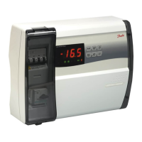
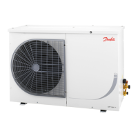
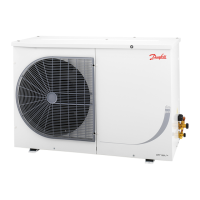
Optyma Plus
TM
User Guide RS8GD602 © Danfoss 2015-10 9
Select signal for the display
Here you dene the signal to be shown by the display.
1: Suction pressure in degrees, Ts.
2: Condensing pressure in degrees, Tc.
o17 Display mode
Pressure transmitter settings for Ps
Working range for pressure transmitter - min. value
o20 MinTransPs
Pressure transmitter settings for Ps
Working range for pressure transmitter - max. value
o21 MaxTransPs
Refrigerant setting (only if "r12" = 0)
Before refrigeration is started, the refrigerant must be dened. You may choose be-
tween the following refrigerants
2=R22. 3=R134a. 13=User dened. 17=R507. 19=R404A. 20=R407C. 21=R407A.
37=R407F.
Warning: Wrong selection of refrigerant may cause damage to the compressor.
Other refrigerants: Here Setting 13 is selected and then three factors -Ref.Fac a1, a2
and a3 - via AKM must be set.
o30 Refrigerant
Digital input signal - D2
The controller has a digital input 2 which can be used for one of the following func-
tions:
0: The input is not used.
1: Status display from an external safety function (short-circuited =ok for compressor
operation)
2: Main switch. Regulation is carried out when the input is short-circuited, and regula-
tion is stopped when the input is put in pos. OFF.
3: Night operation. When the input is short-circuited, there will be regulation for night
operation.
4: Separate alarm function. Alarm will be given when the input is short-circuited.
5: Separate alarm function. Alarm will be given when the input is opened.
6: Input status, on or o. (DI2 status can be tracked via data communication)
7: Alarm from the compressor's external speed control.
o37 DI2 cong.
Pressure transmitter settings for PC
Working range for pressure transmitter - min. value
o47 MinTransPc
Pressure transmitter settings for PC
Working range for pressure transmitter - max. value
o48 MaxTransPc
Select the type of condensing unit.
Factory set.
After the rst setting, the value is 'locked' and can only be changed once the control-
ler has been reset to its factory setting.
When entering the refrigerant setting, the controller will ensure that the 'Unit type'
and refrigerant are compatible.
o61 Unit type
S3 Conguration
0 = S3 input not used
1 = S3 input used for measuring of discharge temperature
o63 S3 cong
Save as factory setting
With this setting you save the controller’s actual settings as a new basic setting (the
earlier factory settings are overwritten).
o67 -
Dene the use of the Taux sensor (S5)
0: Not used
1: Used to measure oil temperature
2: Other use. Measuring of optional temperature.
o69 Taux Cong
Period time for heating element in crankcase
Within this period the controller will itself calculate an OFF and ON period.
The time is entered in seconds.
P45 PWM Period
Dierence for the heating elements 100% ON point
The dierence applies to a number of degrees below the 'Tamb minus Ts = 0 K' value.
P46 CCH_OnDi
Dierence for the heating elements full OFF point
The dierence applies to a number of degrees above the 'Tamb minus Ts = 0 K' value
P47 CCH_ODi
Operating time for condensing unit
The condensing unit's operating time can be read out here. The read-out value must
be multiplied by 1,000 in order to obtain the correct value.
(The displayed value can be adjusted if required)
P48 Unit Runtime
Operating time for the compressor
The compressors operating time can be read out here. The read-out value must be
multiplied by 1,000 in order to obtain the correct value.
(The displayed value can be adjusted if required)
P49 Comp Runtime
Operating time for heating element in crankcase
The heating element's operating time can be read out here. The read-out value must
be multiplied by 1,000 in order to obtain the correct value.
(The displayed value can be adjusted if required)
P50 CCH Runtime
Number of HP alarms
The number of HP alarms can be read out here.
(The displayed value can be adjusted if required)
P51 HP Alarm Cnt
 Loading...
