© Danfoss A/S (RA Marketing/MWA), Nov. 08 RS8FE102, 080R9278 11
OPTYMA
TM
Control three-phase Operation and Maintenance Guide
10.
Using the holes made in point 9 above, screw the
back panel to the wall using 4 screws of a suitable
length for the wall thickness. Fit a rubber washer
(supplied) between each screw and the housing
back panel.
Installing the unit
(continued)
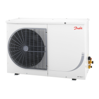
11.
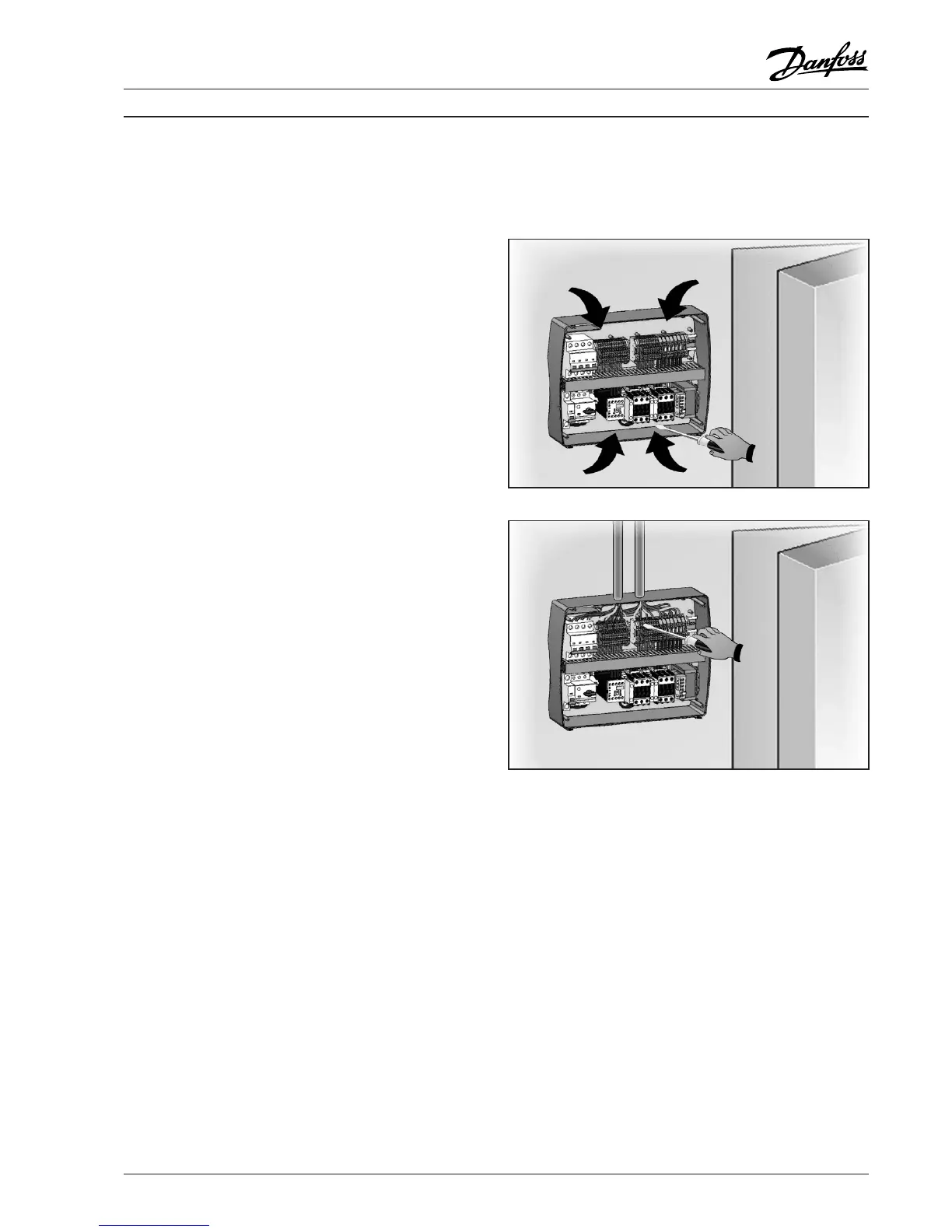
Now do the electrical wiring as shown below.
Electrical wirings
• For the electrical wiring please refer to the wiring
instruction and technical characteristics of the
controller being installed.
• The controller power supply must be on a
dedicated line, and must be equipped with a
suitable device to protect against indirect contacts
upstream of the line (differential interrupter).
• Do not route power supply wiring and signal
wiring (probes/sensors and digital inputs)
in the same raceways or ducts.
• Do not use multi-polar cables which have wires
connected to inductive/power loads and signalling
wires (e.g. probes/sensors and digital inputs).
• Minimise the length of connector wires so that
wiring does not twist into a spiral shape, as this
could have a detrimental effect on the elec-
tronics.
• If a probe/sensor extension is required, the wires
must have a diameter of at least 1 mm
2
.
• All wiring must be of a diameter suitable for the
relevant power levels. The degree of insulation
must be compatible with the applied voltages.
Preferably use cables with flame-retardant
insulation and a low smoke emission where fire
regulations apply.
• It is essential to connect the clamp marked PE
to the earth of the supply system.
If necessary, please check the eectiveness of
the earthing system.
• Do not connect to the PE clamp conductors
any dierent than the external protection.