6
180R9267 / IOM APP 1.5-3.5 Appendices - v04 / 11.2013
Data sheet APP pumps - APP 1.5-3.5
4
521B0850 / DKCFN.PD.013.FA6.02 / 09.2012
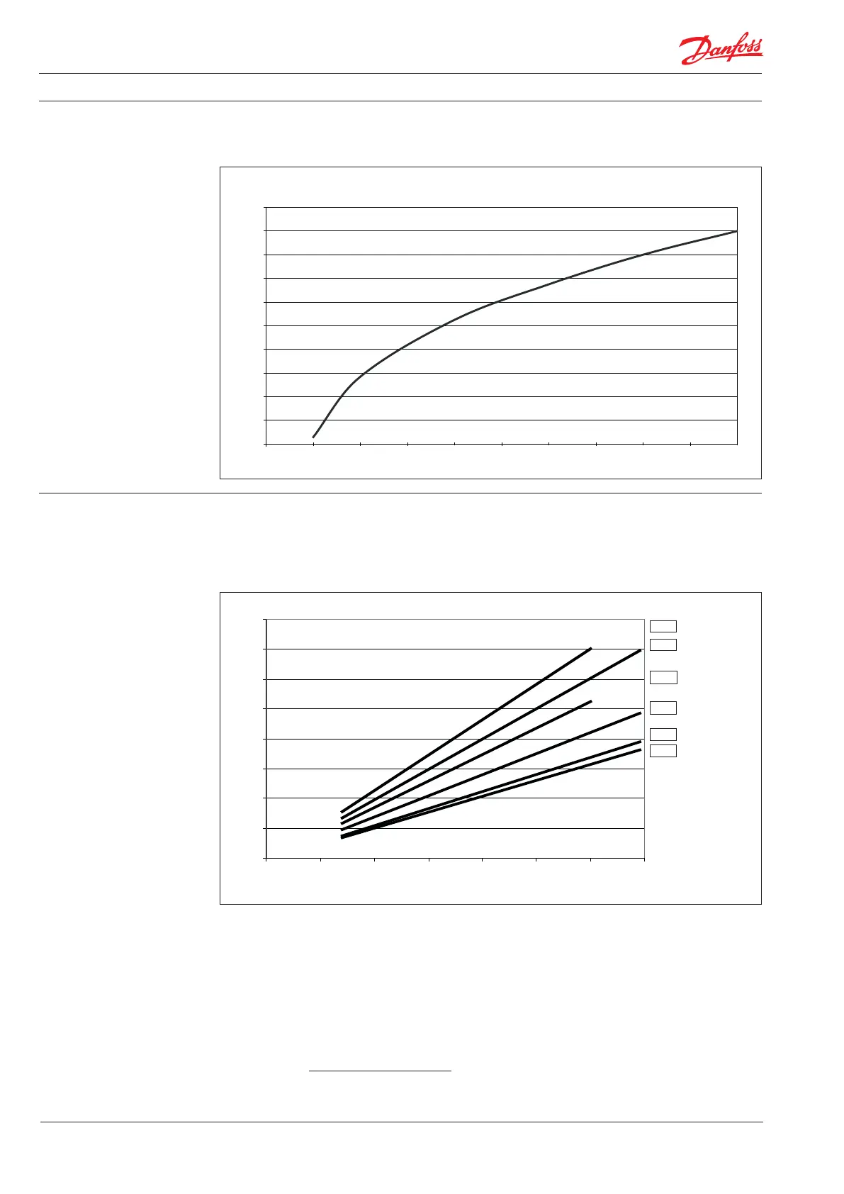
The diagram shows pressure dierences across
the ushing valve:
4. Flushing valve
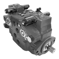
5. Flow at dierent rpm Using the diagram shown below, it is easy to
select the pump which ts the application best if
the ow required and the rotation speed (rpm) of
the pump are known.
Furthermore, this diagram shows that the ow
can be controlled by changing the rotation
speed of the pump. The ow/rpm ratio is
constant, and the “required“ ow can be
obtained by changing the rotation speed to a
corresponding value. Thus, the required rpm can
be determined as:
Required ow × Rated rpm
Required rpm =
Rated ow
521B0850 DKCFN.PD.013.FA6.02 3
5. Flow at diff erent rpm
Using the diagram shown below, it is easy to select the pump which fi ts the application best if the fl ow required and the rotation
speed (rpm) of the pump are known.
Furthermore, this diagram shows that the fl ow can be changed by changing the rotation speed of the pump. The fl ow/rpm ratio is
constant, and the “required “ fl ow can be obtained by changing the rotation speed to a corresponding value. Thus, the required rpm
can be determined as:
Required fl ow × Rated rpm
Required rpm =
Rated fl ow
6. Power requirements
Pump model Flow Pressure rpm Calc. factor
60 bar 70 bar 80 bar
l/min m
3
/h gpm 870 psi 1015 psi 1160 psi
APP1.5 25.11 1.51 6.63 3.21 kW 3.75 kW 4.29 kW 2890 468.6
APP1.5 30.17 1.81 7.97 3.86 kW 4.51 kW 5.15 kW 3470 468.6
APP1.8 26.78 1.61 7.07 3.43 kW 4.00 kW 4.57 kW 2890 463.2
APP1.8 32.18 1.93 8.50 4.12 kW 4.81 kW 5.49 kW 3470 463.2
APP2.2 33.48 2.01 8.84 4.29 kW 5.00 kW 5.71 kW 2900 468.6
APP2.2 40.22 2.41 10.63 5.15 kW 6.01 kW 6.87 kW 3480 468.6
APP2.5 41.94 2.52 11.08 5.07 kW 5.92 kW 6.77 kW 2900 484.8
APP3.0 48.2 2.9 12.7 6.2 kW 7.2 kW 8.2 kW 2930 470.0
APP3.5 56.0 3.4 14.8 7.2 kW 8.4 kW 9.6 kW 2930 470.0
The power requirements can be determined using one of the following guiding equations:
l/min × bar 16.7 × m
3
/h × bar 0.26 × gpm × psi
Required power = [
kW] or [kW] or [kW]
Calc. factor Calc. factor Calc. factor
1 hp = 0.75 kW
1 kW = 1.34 hp
1 gpm = 3.79 l/min
1 l/min = 0.26 gpm
1 m
3
/h = 4.40 gpm
1 gpm = 0.23 m
3
/h
0
0,5
1
1,5
2
2,5
3
3,5
4
0 500 1000 1500 2000 2500 3000 3500
rpm
m³/h
APP1.8
APP2.2
APP1.5
APP2.5
APP3.0
APP3.5
2 DKCFN.PD.013.FA6.02 521B0850
3. Technical data
APP pumps APP1.5 APP1.8 APP2.2 APP2.5 APP3.0 APP3.5
Code number 180B3043 180B3044 180B3045 180B3046 180B3030 180B3032
Geometric displacement
cm
3
/rpm
(in
3
/
rpm)
9.3
(0.56)
10
(0.61)
12.5
(0.76)
15.3
(0.93)
17.7
(1.08)
20.5
(1.25)
Rated fl ow (3000 rpm)
1)
m
3
/h
(gpm)
1.5
(6.6)
1.7
(7.5)
2.1
(9.2)
2.6
(11.4)
3.0
(13.2)
3.5
(15.4)
Outlet min. pressure
2)
bar
(psi)
20
(290)
20
(290)
20
(290)
20
(290)
20
(290)
20
(290)
Outlet max. pressure,
continuous
3)
bar
(psi)
80
(1160)
80
(1160)
80
(1160)
80
(1160)
80
(1160)
80
(1160)
Outlet max. pressure,
intermittent
4)
bar
(psi)
100
(1450)
100
(1450)
100
(1450)
100
(1450)
100
(1450)
100
(1450)
Inlet min. pressure
bar
(psi)
0.5
(7.3)
0.5
(7.3)
0.5
5)
(7.3)
0.5
(7.3)
0.5
5)
(7.3)
0.5
(7.3)
Inlet max. pressure,
continuous
bar
(psi)
5
(72.5)
5
(72.5)
5
(72.5)
5
(72.5)
5
(72.5)
5
(72.5)
Inlet max. pressure, peak
bar
(psi)
10
(145)
10
(145)
10
(145)
10
(145)
10
(145)
10
(145)
Max. speed continuous rpm 3450 3450 3450
5)
3000 3450
5)
3000
Min. speed continuous rpm 700 700 700 700 700 700
Power requirement
at 80 bar and 3000 rpm
kW
(hp)
4.5
(6)
4.8
(6.3)
6.0
(7.9)
7.2
(9.6)
8.4
(11.3)
9.8
(13.1)
Torque at 80 bar
Nm
(lbf-ft)
14,2
(10.5)
15.3
(11.3)
19
(14)
23
(17)
25.6
(18.8)
29.7
(21.9)
Weight
Kg
(lb)
8.6
(17)
8.6
(17)
8.6
(17)
8.6
(17)
8.6
(17)
8.6
(17)
Integrated fl ushing valve YES YES YES YES YES YES
1) Typical average fl ow at 80 bar (1160 psi). 4) Intermittent pressure is acceptable for less than
2) For lower pressure, please contact Danfoss RO Sales Organization.
10 seconds per minute.
3)
For higher pressure, please contact Danfoss RO Sales Organzation.
5) For speeds above 3000 rpm the pump must be
boosted at a pressure of 2-5 bar (29.0 - 72.5 psi).
4. Flushing valve
The diagram shows pressure diff erence across fl ushing valve
APP1.5-3.5 flushing valve characteristic
0
2
4
6
8
10
12
14
16
18
20
Pressure [bar]
Flow[l/min]
APP 1.5-3.5 ushing valve characteristic
Pressure [bar]
Flow [l/min)
20
18
16
14
12
10
8
8
4
2
0 1 2
2 3 4 5