11
180R9267 / IOM APP 1.5-3.5 Appendices - v04 / 11.2013
Data sheet APP pumps - APP 1.5-3.5
8
521B0850 / DKCFN.PD.013.FA6.02 / 09.2012
10.2 Complete unit
Pump A
(mm)
B
(mm)
C
(mm)
D
(mm)
E
(mm)
F
(mm)
G
(mm)
H
(mm)
IEC Electric motor
APP 1.5 250 260 100 160 140 325 120 166 3.0 kW, IEC 100L-2
APP 1.8 250 290 112 190 140 340 120 166 4.0 kW, IEC 112M-2
APP 2.2 300 338 132 216 140 403 144 166 5.5 kW, IEC 132S1-2
APP 2.5 300 338 132 216 178 403 144 166 7.5 kW, IEC 132S2-2
APP 3.0 350 422 160 254 210 505 188 166 11 kW, IEC 160M1-2
APP 3.5 350 422 160 254 210 505 188 166 11 kW, IEC 160M1-2
11. Installation 11.1 Mounting
The gure below illustrates how to mount the
pump and connect it to electric motor/combus-
tion engine.
A: Flexible coupling
B: Bell housing
C: Motor shaft
If alternative mounting is required, please
contact Danfoss Sales Organization for further
information.
To ensure easy mounting of the exible coupling
without using tools, the tolerances must be
dimensioned accordingly.
Note: Any axial and/or radial loads on the shaft
must be avoided.
The pump should be connected to the rest of the
plant with exible hoses.
A CB
Min. 5 mm
Data sheet APP pumps - APP 1.5-3.5
9
521B0850 / DKCFN.PD.013.FA6.02 / 09.2012
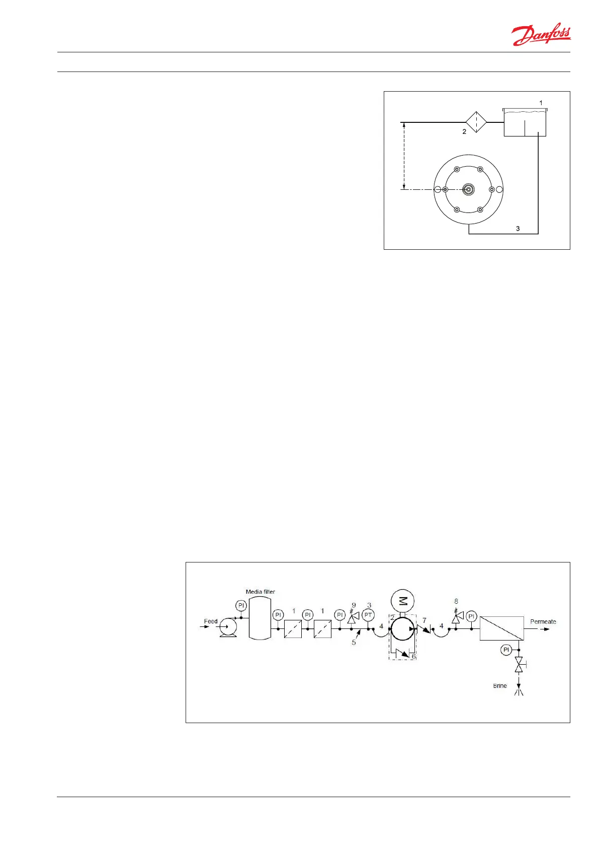
11.2 Open-ended system with direct water
supply
In order to eliminate the risk of cavitation, a
positive inlet pressure is always to be main-
tained. Please see technical data (part 3.) for
specic pressure values.
1. Place the lter (1) in the water supply line in
front of the pump.
2. Place a monitoring pressure switch (2) - set
at min. inlet pressure - between lter and
pump inlet. The monitoring switch must
stop the pump at pressures lower than min.
inlet pressure. Please see technical data
(part 3.) for specic pressure values.
11.3 RO system with APP pump
1. Dimension the inlet line to obtain mini-
mum pressure loss (large ow, minimum
pipe length, minimum number of bends/
connections and ttings with small
pressure losses).
2. Place an inlet lter (1) in front of the APP
pump (2). Please consult section 9,
“Filtration” for guidance on how to select
the right lter. Thoroughly clean pipes and
ush system prior to start-up.
3. Place a monitoring pressure switch (3) set
at min. inlet pressure between lter and
pump inlet. The monitoring switch must
stop the pump at pressures lower than
minimum pressure.
4. Use exible hoses (4) to minimize vibrations
and noise.
5. In order to eliminate the risk of damage
and cavitation, a positive pressure at the
inlet (5) is always to be maintained at min.
inlet pressure and max. inlet pressure.
6. For easy system bleeding and ushing, a
bypass non-return valve (6) is integrated in
the APP pump.
7. A non-return valve (7) in outlet can be
installed in order to avoid backspin of the
pump. The volume of water in the
membrane vessel works as an accumulator
and will send ow backwards in case of the
pump stops momentarily.
8. A safety valve (8) can be installed in order
to avoid system damage as the Danfoss
APP pump creates pressure and ow
immediately after start-up, regardless of
any counter-pressure.