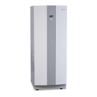
3.3 DHP-C
110
1845 (±10)
455
596
528
300
440
40±10
2
1
610
80
4
7
8
6
5
3
Figure 3. Dimensions and connections
Symbol explanation
1 Brine in, 28 Cu
2 Brine out, 28 Cu
3 Heating system supply pipe, 22 Cu
4 Heating system return pipe, 22 Cu
5 Connection for bleed valve, 22 Cu
6 Hot water line, 22 mm
7 Cold water line, 22 mm
8 Lead-in for supply, sensor and communication cables
The brine pipes can be connected on either the left or right-hand sides
of the heat pump.
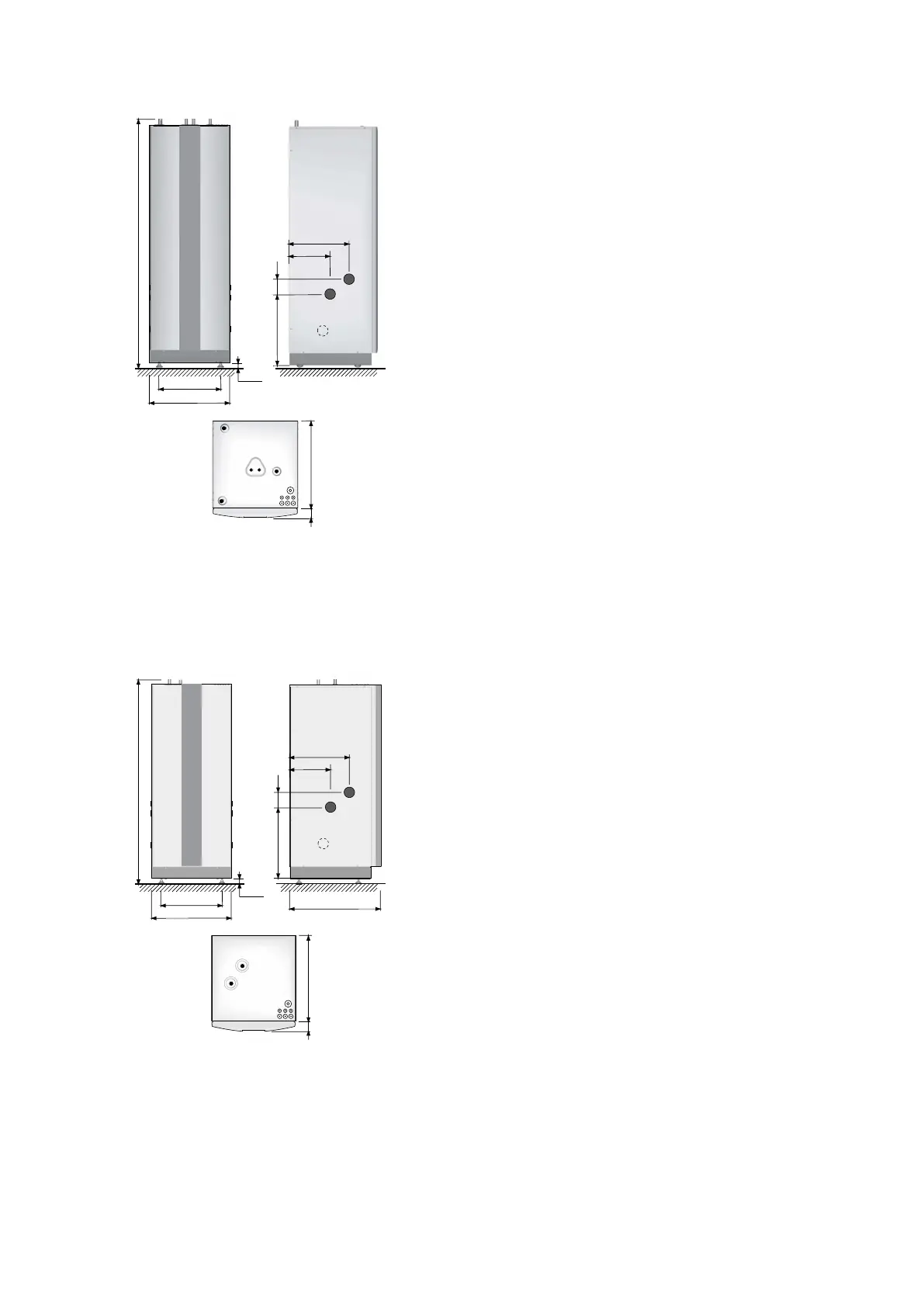
3.4 DHP-L, DHP-L Opti
1538 (±10)
455
596
690
40±10
110
528
300
440
1
2
610
80
3
5
4
Symbol explanation
1 Brine in, 28 Cu
2 Brine out, 28 Cu
3 Heating system supply pipe, 22 Cu: 4-10 kW, 28 Cu:
12-16 kW
4 Heating system return pipe, 22 Cu: 4-10 kW, 28 Cu: 12-16
kW
5 Lead-in for supply, sensor and communication cables
The brine pipes can be connected on either the left or right-hand sides
of the heat pump.
Installation instructions VMBMA1002 – 11
 Loading...