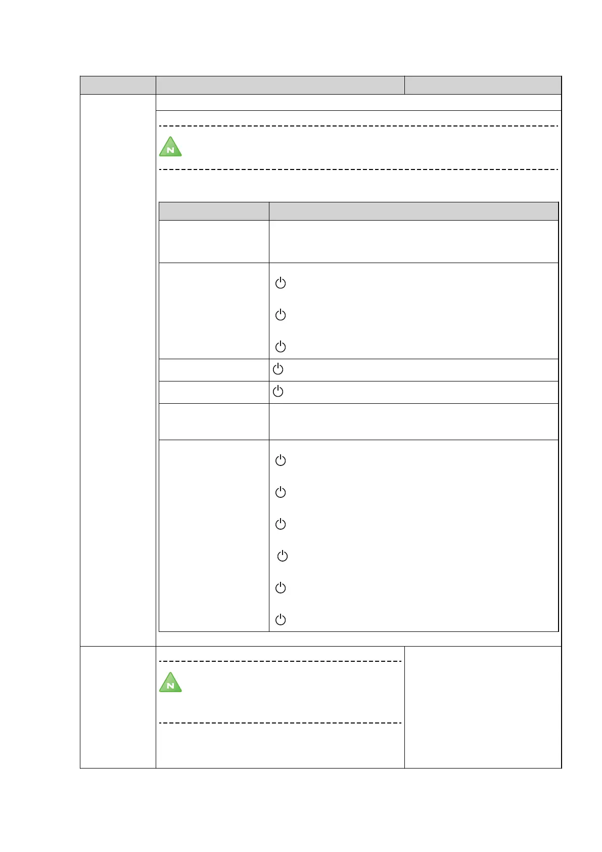
9.5 Sub-menu INSTALLATION
Table 21. Used for settings that are set during installation.
Menu selection Meaning Factory setting
SYSTEM Sub menu SERVICE -> INSTALLATION -> SYSTEM:
Note! The menu selection in the SYSTEM menu varies depending on the selected
values. Tip: start in the top menu and work downwards.
Menu selection Meaning
HEAT SOURCE GROUND OR ROCK
OUTSIDE AIR
(BRINE SOLUTION, DIRECT EVAP.)
COOLING PASSIVE COOLING
( , EXTERNAL, INTEGRATED IN HP)
COOLING A
( , EXTERNAL)
ROOM SENSOR
( , ON)
POOL
, ON
SHUNT GROUP
, ON
BUFFER TANK (See sepa-
rate instruction for buffer
tank)
BUFFER TANK
SYSTEM SHUNT
2ND H.C SHUNT
ADDITION OPTIMUM
( , ON)
HGW
( , ON)
0-10V
( , EXT. AUX. HEATER)
FLOW SENSOR
(
, ON)
CURRENT LIMITER
(
, ON)
PHASE FAULT
(
, PHASE READING)
SERVICE TIME
Note! Only used for test operation. The heat
pump counts 60 times as fast, which means that
the waiting times are eliminated during test
operation.
0 = deactivates SERVICE TIME
1 = activates SERVICE TIME, which speeds up the control sys-
tem’s integral calculation and start delay by 60 times.
-
58 – Installation instructions VMBMA1002
 Loading...