EasyManua.ls Logo

Danfoss DLX 2.0 UL

Danfoss DLX 2.0 UL
95 pages
To Next Page IconTo Next Page
To Previous Page IconTo Previous Page
Loading...
12
2.4.
5
2.4.
5
T
he f
r
The
u
cove
r
The l
o
instal
2.4.6
T
he l
o
calle
d
easy
t
5
.1.
Mec
h
Figu
r
5
.2.
Fron
t
r
ont surface
o
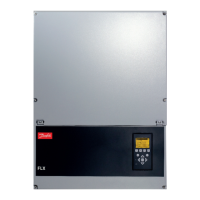
Figure 2.
5
u
pper cover
r
by unautho
r
o
wer cover
p
ler for electri
Rem
o
.
o
wer cover p
d
the Stringb
o
t
o de-energi
z
h
anical Di
e
2.4: Mechanic
a
t
Covers
o
f the invert
e
5
: Inverter struct
u
may be rem
o
r
ized person
s
p
rotects the
c
cal connecti
o
o
ving th
e
rotects the c
o
o
x. The lowe
z
e the DC ter
mension
s
a
l dimensions
e
r consists of
u
re
o
ved by Dan
f
s
voids the
w
c
ustomer co
n
o
n and main
t
e
Lower
C
o
nnection a
r
r cover is eq
u
minals on th
e
s
H: 28.
3
W:13.
9
D: 6.2 i
an upper an
d
1. U
p
2. Di
s
3. Lo
w
s
w
4. H
o
f
oss authoriz
e
w
arranty!
n
nection are
a
t
enance.
C
over
r
ea in the inv
e
u
ipped with
a
e
inverter.
U
3
inches / 720
m
9
inches / 353
m
i
nches / 158
m
d
a lower co
v
p
per cover
s
play
w
er cover wit
h
w
itch
o
le covers (Kn
o
e
d persons o
a
, and may b
e
rter and als
o
a
DC switch
o
ser Guide DLX UL
m
m
m
m
m
m
v
er.
h
DC disconn
e
o
ckouts)
nly. Remova
e removed
b
o
the inbuilt
c
o
n the front,
w
series L00410625-
0
e
ct
l of the upp
e
b
y the syste
m
c
ombiner b
o
w
hich make
i
01
e
r
m
o
x
i
t

Table of Contents

Other manuals for Danfoss DLX 2.0 UL

Related product manuals